Extending gear life on SAG Mills, Ball Mills and Kilns using Thermal imaging techniques
InfraMation 2016 Application Paper Submission
Chuck Strait
Petron Corp
ABSTRACT
Your SAG Mill, Ball Mill or Kiln has shown a possible misalignment or lubricant issue in the gear mesh using the conventional IR temperature meters. You must now determine just how bad it is. Does it need to be fixed immediately, or can it wait a few days, a few weeks?
INTRODUCTION
In very large gear-sets like those used in SAG Mills, Ball Mills and Kilns, IR surveys are used as an efficient means of identifying problems under full load operating conditions. This equipment rarely shuts down for physical inspection of the gears and it is possible to glean a much better snap shot of how they are doing by inspecting them while rotating under normal operation. The Thermal camera has become to go to tool to capture this snap shot.
TEMPERATURE BELL CURVE
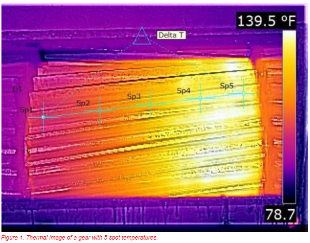
Traditionally when someone wanted to trend how a large gear-set is performing the use of permanent UDTs or hand held IR meters were used at five locations along the root of the pinion gear. These five temperatures when plotted on the graph will typically look like a standard bell curve.
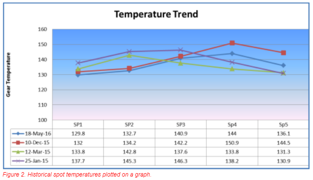
Where the high point on the bell curve is located will tell you where the load on the mill/kiln is located. If the high point is closer to the bull gear (used to refer to the larger of two spur gears that are in engagement in any machine. The smaller gear is usually referred to as a pinion) then the mill/kiln is lightly loaded or has lower than expected throughput, but still in alignment. If the high point is closer to the right hand side of the gear it is considered to be aligned for the load that is currently going through the mill/kiln.
The Delta Temp is measured from the extreme left hand edge of the gear compared with the extreme right hand edge. This is the typical number used to determine if the gear set is in alignment. If the Delta Temp is 15 Deg F or less it is considered in good alignment. 15 Deg F to 30 Deg F would cause some concern as a Delta Temp of that size is considered more than normal, but you would not typically see usual wear for a long period of time. More than 30 Deg F, Delta Temp would require immediate investigation. Continued running at that alignment could lead to very rapid metal loss and gear profile deterioration.
WHY THE THERMAL CAMERA EXCELS IN TRENDING GEAR ALIGNMENT?
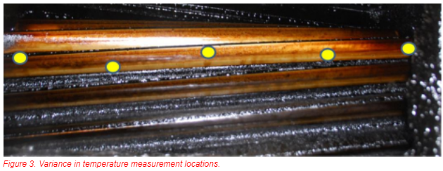
When a traditional method of IR trending is done on gear set, the IR device takes an average temperature inside a large spot located on a gear tooth. This temperature is also averaged over each and every gear tooth on the pinion. Using permanently mounted IR devices will yield a pretty good approximation of gear tooth temperatures. But when using hand held devices all data is directly proportional to the skill and repeatability of the operator. As seen in the photo below, any variance either above or to the side of the previous locations measured can get dramatically different temperatures than the true temperature.
A good thermal image of a gear tooth will give the end user a much better idea of what is actually happening. The temperatures recorded are not averaged over a large area or averaged over multiple teeth. The operator can be very precise as to the location on the gear face he would like specific temperatures with little chance of being over or on the side of the tooth.
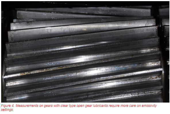
The thermal camera will generate the best visible (as opposed to thermal) image if you can get plenty of light on the subject. The better the light the better the contrast. Many gear-sets will be lubricated with residual type open gear lubricants (OGL) that are dark and opaque. This renders very good temperature profiles (due to the higher emissivity) but sacrifices visual image quality due to them being hard to light up significantly. See Figure 3 above.
Clear type open gear lubricants will render very good thermographic images but care needs to be taken to ensure the emissivity is correctly set or your temperature readings will be considerably off.
KEY STEPS TO GET ACCURATE RESULTS
Identify the environment in which the gear set is operating. You must identify all of the factors that can alter your ability to accurately measure the real gear tooth temperature. When setting up your camera it is very important to measure your ambient and reflected temperatures. Reflected temperatures can vary dramatically on kilns due to their high operating temperatures. Reflected temperatures on Ball Mills and Sag mills can be affected due to space heaters and other localized heat sources.
The Open Gear lubricant will have an emissivity near 0.95 for residual type lubricants but can be almost anything from 0.40 to 0.95 for clear type lubricants. The root temperature and the gear face temperature will be very similar with residual lubricants. The root temperature on a gear lubricated with a clear lubricant will give a much better result than the gear face due to the contamination in the roots adding to the emissivity of the area. The highly reflective nature of the clear OGL on the gear face make temperature recording in this area very difficult to do precisely. One method you can use is to take a piece of electrical tape and attach it to the load zone of the pinion gear and record a “constant” temperature using .95 emissivity setting. Then adjust the emissivity setting until the areas just left and right of the electrical tape show the “constant” temperature. This will be your new emissivity setting for a particular lubricant with a normal amount of contamination trapped in the lubricant film.
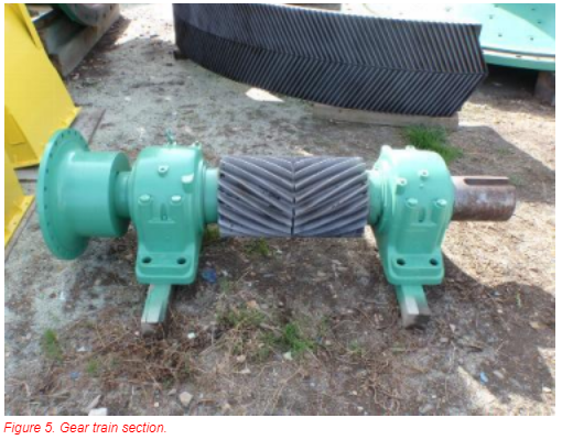
See Figure 5 above, the alignment of the drive shafts from the inboard support bearing through the pinion and on through the outboard bearing is also important to eliminate a possible hidden heat source. With a standard IR hand held meter the temperatures have to be much higher before an issue will be observed. But, when using a thermal camera, it is easy to identify a bearing that needs more lubricant or a bearing race that is rubbing on the drive shaft causing a high temperature load zone. This higher temperature will migrate down the length of the drive shaft and be added to the pinion temperatures.
The thermal image itself should show the higher temperatures just to the shell side of the pinion on Ball and SAG mills and an elevated area on the up-hill side of the kiln gears if the gear set is aligned for the throughput load seen during operation.
If the temperature profile is more linear than a bell curve, then the pinion is not aligned to the bull gear for the current load. The greater the difference of temperatures from left edge to right edge, the more out of alignment the pinion is to the bull gear.
If the temperature profile is almost flat, then typically the gear set has not run long enough to generate accurate temperatures. Your first step would be to compare gear temperatures to ambient temperature. If the two temperatures are within 20 Deg F, then the gear set has not reached normal operating conditions.
SUMMARY
The use of a thermal camera has revolutionized the inspection of large gear sets like those seen on SAG Mills, Ball Mills or Kilns. A thermal camera generates a “snap shot” of the gear in real time conditions that will allow a maintenance department to make informed decisions about what adjustments need to be made.
ABOUT THE AUTHOR
Chuck is a Level I thermographer that has been published in World Cement and worked as a Reliability Engineer in Mining and heavy industry for 20 years.
Related Articles
-
 Electrical/Mechanical
Mechanical Applications for Industrial Infrared
Read the Story -
 Electrical/Mechanical
Interesting IR Opportunities Found Over 14 years as a Distribution Line and Substation Thermographer
Read the Story -
 Electrical/Mechanical
Maximizing the Return on your Infrared Electrical Inspection Investment
Read the Story