Aerial Substation Thermography
InfraMation 2018 Application Paper Submission
Dusty L Birge
Founder – UAV Recon
ABSTRACT
Electrical substations are critical infrastructure whose maintenance process is imperative in prolonged lifecycle and grid reliability. Ground-based thermography has been the primary means for IR data collection on substation equipment. Now, electric utilities are seeing positive returns and more effective thermography data as a result of advancements in remotely operated unmanned aerial systems.
INTRODUCTION
UAV Recon founder, Dusty Birge, is a niche sUAS solutions provider for electrical power utilities, with a prior background in electrical infrastructure. UAV Recon has flown over 1,000 miles of powerline and completed thermography inspections on over (120) substations and circuit switches. Most thermography work has been completed at nighttime, permitted as part of an FAA Part 107.29 Daylight Operations Waiver. UAV Recon operates the FLIR Zenmuse XT 640x512 – 19mm Radiometric sensor on a DJI Matrice 100 airframe.
Most electrical contractors or service companies already have ground-based thermography contracts, many of which whose clients are satisfied with the inspection findings. Many utilities also own a hand-held thermography camera.
Why should one consider aerial thermography? What if you already have an IR camera?
A summary of abbreviations used in this manuscript:
FAA – Federal Aviation Administration
Part 107 – FAA Regulations for Small Unmanned Aircraft Systems (sUAS)
sUAS – Small Unmanned Aircraft System (commonly known as a ‘drone’)
IR – Infrared Radiation
SSR – Spot Size Ratio; Cameras Maximum Distance to Reliably Measure Temperature
kV – Common Unit of Measurement of Electrical Components (1kV = 1000 volts)
WHY AERIAL THERMOGRAPHY?
The view up there is amazing, very detailed, and quite comprehensive.
Even with a properly tuned camera, ground-based operators are often limited on available inspection angles for overhead equipment. Access can also be limited due to minimum approach distances on energized equipment.
Since much of the equipment in a substation is 3 phase, relative thermography is often sufficient in discovering advisories, especially if electrical load in the substation is high (>70% of total capacity). However, when absolute temperatures are needed, an aerial view can produce excellent results.
Utilizing the FLIR XT, aerial thermography has proved successful in substation & utility applications.
The main benefits an operator may experience with an aerial platform include, but not limited to:
• Automatic Focus → Quicker Recording, Auto Focus, Level, & Span
• View from Above → Excludes Sky, Auto Span Often Less Than 25o
• Larger Field of View → Method of Scan vs Point & Shoot
• Unlimited Positioning → High Accuracy = Absolute Thermography
• Live HD Streaming → Realtime Collaboration & Analysis
• Embedded GPS Coordinates → Simplified Recording Procedures
Thermographers are taught Focus, Range, SSR, and Distance are among the most critical factors in capturing quality data. Similarly, achieving a sufficient angle (absolute temperature measurements) is just as important for capturing quality data (Figure 1.0). For the extent of this manuscript, the color pallet used displays low temperature values as dark shades, and high temperature values as brighter shades.
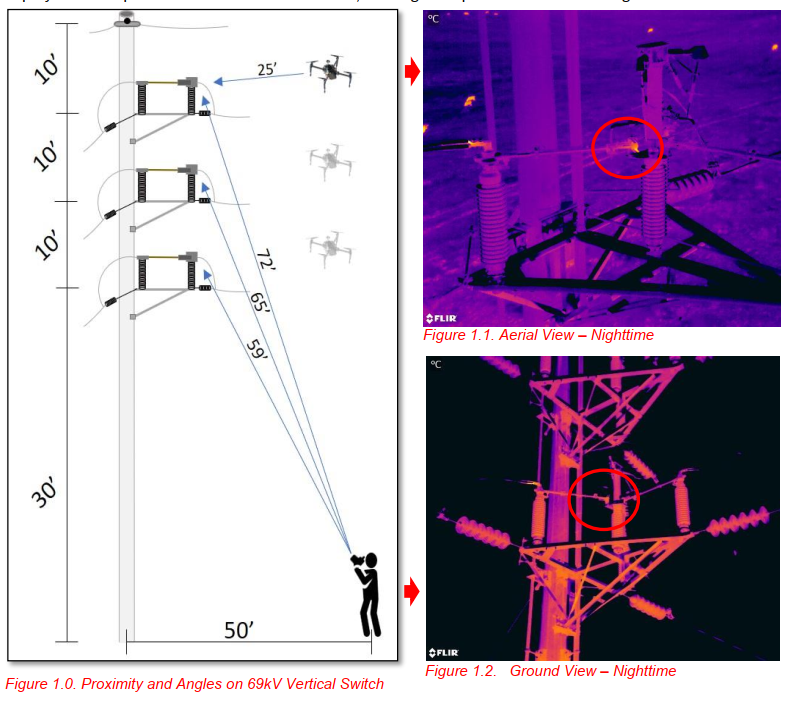
Figure 1.0 illustrates the proximity and angle advantages of an aerial view, most importantly the hot spot (Figure 1.1) inside the switch fingers, which was not visible from the ground (Figure 1.2), due to an angle limitation. The downward angle of the aerial view (Figure 1.1), completely excludes the sky from the field of view, resulting in detecting minor temperature deltas. In contrast, the upward angle (Figure 1.2) indicates reflection from the warm asphalt below the switch, portraying most of the switch as ‘warm.’ Auto focus, span, and range are features of the FLIR XT camera. If absolute temperature measurements were required, spot-size-ratio is a fixed camera characteristic and the ground-based operator may be limited in attaining adequate distance (Figure 1.0). However, the sUAS platform can maneuver to attain necessary distance, and exclude the sky.
* Figure 1.0 is an illustration of a 69kV switch, actual measurements vary, for reference only
PROCEDURE
Since we often conduct nighttime inspections, this basic procedure can be used to collect data similar to the subsequent case studies with circuits at least 70% of max capacity. Adhere to FAA Part 107.
Daytime Assessment
a. Safety Meeting & Review Scope with Participants
b. Record Overhead Obstructions & Precautions
c. Determine Flight Path & Proximity Limits - Manual Flight
d. Perform Aerial Visual Inspection (High-Res RGB Visual Sensor)
e. Document Nighttime Plan, Precautions, & Situational Awareness Aids
Nighttime Assessment
a. Safety Meeting & Review Scope with Participants
b. Confirm Location of Overhead Obstructions, Precautions, & Situational Aids
c. Repeat Flight Path - Manual Flight
d. Record Weather Conditions & Capture Calibration Image
e. Perform Aerial Nighttime Inspection (IR Thermal Sensor)
f. Record Inspection Summary for Post Project Analysis
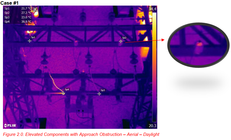
Figure 2.0 illustrates multiple advisories, which were unable to be captured by a ground-based operator due to angle and overhead obstructions. The arrestor on the right (Sp2), shows 6o delta compared to Sp1. Further diagnosis revealed arrestor at Sp2 needed replaced. Also discovered was a loose and pitting connection detected in Sp4, a 14o delta as compared to Sp3; also, later repaired. The ability to position the sUAS with a thermal sensor payload, allows one to navigate obstructions. With real-time assessment and a large screen, the FLIR XT features make detection of advisories easy to record.
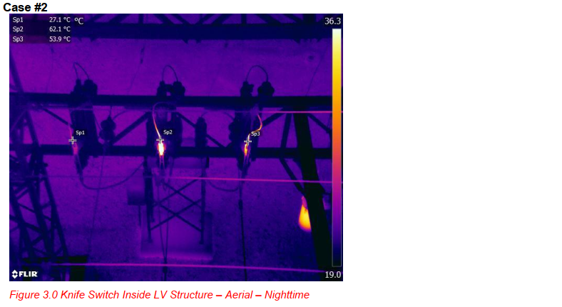
These switches were located inside the low voltage structure, with near impossible access via groundbased operator adhering to minimum approach distances. This 35o delta proved to be a significant advisory prior to summer loading. An aerial view located this advisory, determining both switches had loose clamp hardware. As seen in Figure 3.1, (visual image of Figure 3.0) the advisory location was visible from the outside, however, due to angle, the operator was unable to assess a likely cause. The substation transformer was also in the background of this operators’ angle, affecting his span. Being able to determine a cause or probable resolution prior to de-energizing the substation is very valuable to utilities.

FAA Part 107.29 waiver requirements for nighttime operations require a daytime assessment of the flight area for planning and safe flight operations. Thus, UAV Recon conducts an aerial visual assessment of the substation. Noted above in the red circle (Figure 3.1), a broken insulator was identified. Not detected by either aerial or ground-based thermographer, visual inspections are also important.
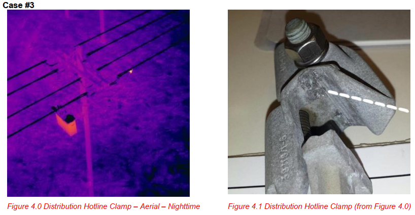
During commencement of flight operations at a 69kV substation, the wide field of view immediately revealed a hotspot outside the substation on the outgoing distribution line. Not within inspection scope, a photo recorded the location, and utility was later advised. See Figure 4.1. To confirm the advisory, the utility later replaced this clamp and discovered the beginning stages of pitting between the conductor and the clamp. Early detection of this advisory was merely by accident, but was discovered as a result of an aerial view.
SUMMARY
Conducting substation inspections with an aerial platform, which includes both a nighttime thermal & daytime visual assessment, can provide utilities the most comprehensive overview of the substation components. Ground-based methods are valuable and often used in conjunction with a sUAS platform. Although thermography is very beneficial, those seeking the most comprehensive method to address proactive substation maintenance should consider adding an sUAS platform to the toolbox. Take advantage of the additional high-resolution visual benefits aerial inspections have to offer, while increasing safety and productivity.
A nighttime assessment can significantly reduce thermal loading caused by daytime conditions, resulting in higher analysis accuracy, quicker advisory detection, and much simpler recording.
ACKNOWLEDGEMENTS & REFERENCES
Thank you to Midwest Electric Cooperative in Grant, Nebraska and Southwest Public Power District in Palisade, Nebraska for collaboration and permission to use images in this manuscript. UAV Recon wishes to thank the Infrared Training Center for providing the resources to make this work possible. We are also grateful for the support of FLIR Systems who manufacture great products.
ABOUT THE AUTHOR
Dusty is a Level I thermographer, with emphasis on Aerial Thermography in Electric Utility applications. Prior to UAV Recon, Dusty was part of (GE) General Electric’s Industrial Solutions business, a leading manufacturer and service entity for industrial LV – HV electrical components and equipment.

