Infrared Thermography at the Savannah River Site
InfraMation 2004 Application Paper Submission
David Gleaton
Savannah River Site
ABSTRACT
The Savannah River Site (SRS) is a Department of Energy (DOE), government-owned, company-operated (GOCO) industrial complex built in the 1950s to produce materials used in nuclear weapons. Five reactors were built to support the production of nuclear weapons material. Irradiated materials were moved from the reactors to one of the two chemical separation plants. In these facilities, known as “canyons,” the irradiated
fuel and target assemblies were chemically processed to separate useful products from waste. Unfortunately, the by-product waste of nuclear material production was a highly radioactive liquid that had to be stored and maintained. In 1993 a strategy was developed to implement predictive maintenance technologies in the Liquid Waste Disposition Project Division responsible for processing the liquid waste. Responsibilities include the processing and treatment of 51 underground tanks designed to hold 750,000 to 1,300,000 gallons of liquid waste and operation of a facility that vitrifies highly radioactive liquid waste into glass logs. Electrical and mechanical equipment monitored at these facilities is very similar to that found in non-nuclear industrial plants. Annual inspections are performed on electrical components, roof systems, and mechanical equipment. Troubleshooting, post-installation, and post-maintenance infrared inspections are performed as needed. In conclusion, regardless of the industry, the use of infrared thermography has proven to be an efficient and effective method of inspection to help improve plant safety and reliability through early detection of equipment problems.
INTRODUCTION
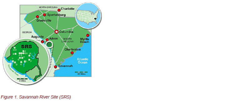
The Savannah River Site, located in South Carolina, is a Department of Energy industrial complex that has produced nuclear materials for national defense, research, and medical programs. The SRS complex covers 198,344 acres or 310 square miles, bordering the Savannah River and encompassing parts of Aiken, Barnwell, and Allendale counties. SRS processes and stores nuclear materials in support of the national defense and U.S. nuclear non-proliferation efforts. The site also develops and deploys technologies to improve the environment and treat nuclear and hazardous wastes from the Cold War.
HISTORY
During the early 1950s, the Savannah River Site began to produce materials used in nuclear weapons, primarily tritium and plutonium-239. Five reactors were built to produce nuclear materials. Support facilities were also built to include two chemical separation plants, a heavy water extraction plant, a nuclear fuel and target fabrication facility, a tritium extraction facility, and waste management facilities. Irradiated materials were moved from the reactors to one of the two chemical separation plants. In these facilities, known as “canyons,” the irradiated fuel and target assemblies were chemically processed to separate useful products from waste. After refinement, nuclear materials were shipped to other DOE sites for final application. The SRS produced about 36 metric tons of plutonium from 1953 to 1988.
WASTE TANK STORAGE
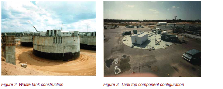
The waste by-product from the two separation facilities (F-area and H-area) has been stored on site for the past 50 years. There are approximately 38 million gallons of high-level radioactive waste currently stored in 49 underground waste storage tanks. In addition, there are two waste storage tanks that have been emptied and closed, totaling 51 original tanks. The waste storage tanks are located at two site locations called F-area and H-area “Tank Farms.”
The tanks are constructed of carbon steel and range in size from 75 feet in diameter by 24½ feet high with 750,000-gallon capacity up to 85 feet in diameter by 34 feet high with 1.3 million-gallon capacity. While the waste is stored in the tanks, it separates into two parts: a sludge that settles on the bottom of the tank and a watery supernate that floats on top of the sludge. The waste is reduced to about 30% of its original volume by evaporation. The watery portion of the supernate is separated from the entrained radionuclides that are captured in the concentrate. The concentrate forms solid saltcake, making it less likely to escape to the environment in the event of a tank crack or leak. SRS currently has three evaporators operating to maintain volume reduction capabilities.
IMPLEMENTATION OF INFRARED INSPECTION
The High Level Waste (HLW) Management Division is reponsible for storage and processing of high-level radioactive liquid waste at SRS. In 1993 HLW developed a predictive maintenance (PdM) program in response to a directive by the DOE to implement “best practices” for maintenance within the DOE complex. A Reliability Centered Maintenance (RCM) analysis, similar to those used in the commercial and nuclear power
industries, was completed. The RCM determined the applicability of predictive technologies such as vibration analysis, oil analysis, and infrared thermography. During that process, equipment was purchased and individuals selected to implement the program.
The predictive maintenance program was developed to provide equipment condition monitoring rather than time-based inspection and overhaul. Thermography was determined to be an effective tool for detecting certain failure mechanisms in electrical distribution equipment and rotating machinery. The thermography program began with annual inspection of all accessible mechanical and electrical equipment associated with “tank top” process systems. Visual and thermal images of key tank top components are illustrated along with a description of their functions.
Waste Tank Annulus Ventilation System
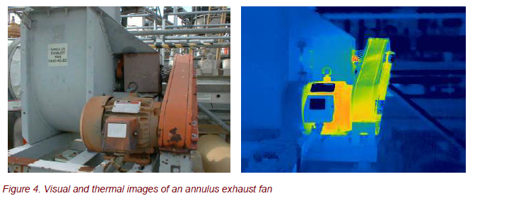
The primary tank or “shell” is the component of the tank that actually contains the liquid waste. The secondary containment of a waste tank provides a location for collection of leakage from the primary tank shell. The annulus is the space between the primary shell and secondary containment. The annulus provides a path for ventilation flow around and under the primary tank to cool the tank and to dehumidify the air around the tank. Air is dehumidified and heated by steam to minimize the amount of corrosion in the annulus and to stop any leak sites. Annulus fans located on the tank top provide airflow to cool the tank. Thermography is performed to monitor annulus fan bearings and motor faults.
Waste Tank Purge Ventilation Systems
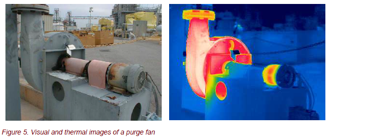
Waste tanks containing radioactive waste generate hydrogen gas. The rate at which the gas is generated is dependent upon several factors, including tank level, nitrate concentration, and tank temperatures. Combustible organic vapors can also potentially build up in the tank vapor space to flammable levels. An exhaust or “purge” fan mounted on the tank top provides a continuous purge of the waste tank vapor space while preventing the release of radionuclides to the atmosphere. Thermography is used to provide a thermal profile of the fan housing, as well as to monitor fan bearings and motor faults.
Cooling Water Systems
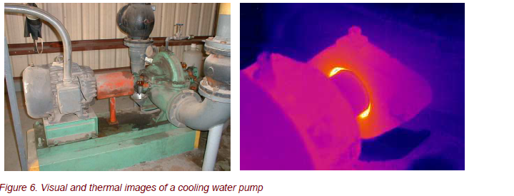
Chromate cooling water coils installed in the tanks remove the decay heat that is generated by the waste. Heat exchangers remove heat from the chromate water using well water in a closed loop system. The chromate water pumps and well water pumps are inspected using thermography to monitor pump bearings, seals, and motor faults.
Slurry Pumps
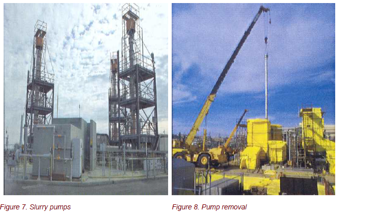
Slurry pumps are used to mix the contents of a waste tank to aid in the removal of the solids from the tank. Pumps located inside the tanks are driven using either 150 or 300 hp motors that are mounted on a motor operated turntable. The turntable rotates the pump, providing a better mixing of the tank contents. The slurry pump and motor are inaccessible for inspection due to radiation conditions; therefore, thermography is limited to inspection of the pump’s electrical components located at the motor control center (MCC).
Electrical Systems
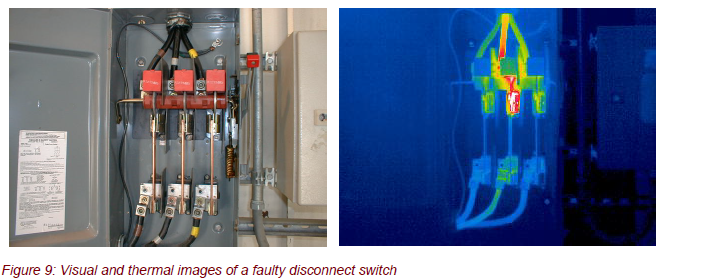
Infrared inspections are performed on electrical components located in the motor control centers that provide power to “tank top” equipment and associated systems. The MCC includes breakers, disconnects, motor starters, panels, relays, and other switchgear for the tank top fans and motors as well as lighting, instrumentation, HVAC (heating, ventilating, and air conditioning), compressors, and emergency back-up power.
CONCLUSION
Prior to the implementation of our predictive maintenance program, all work activities were driven by reactive maintenance as a result of equipment failure. Today, infrared thermography is used to detect electrical fault conditions and complements the vibration analysis program to support identification of mechanical faults. Other applications have proven successful in our thermography program as well, such as detecting wet insulation in roofing systems, determining tank levels, and locating underground steam leaks. The DOE, along with other industries, can no longer support the costs associated with reactive maintenance. Infrared thermography has proven to be a highly effective tool in identifying problems with bearings, seals, belts, motors, and faulty electrical equipment. Our success can be attributed to the dedicated individuals who actually perform the thermography functions and to management support for training to keep the technology growing.

