Lessons Learned Implementing a Mechanical Infrared Program at an Aerospace Testing Facility
InfraMation 2015 Application Paper Submission
Dan Henley, Infrared Program Lead
Aerospace Testing Alliance, Arnold Engineering Development Complex
ABOUT AEDC
The product of Arnold Engineering Development Complex (AEDC) is aerospace test research, development, test, & evaluation data for U.S. Department of Defense (DoD), NASA, and commercial customers across not only this nation but also different parts of the world. Aerospace Testing Alliance (ATA) at AEDC operates and maintains approximately 63 test facilities at Arnold Air Force Base, TN, Tunnel 9 at White Oak, MD, and NFAC at NASA AMES Research Center in CA. AEDC is located on Arnold Air Force Base and is the most advanced and largest complex of flight simulation test facilities in the world. Established in 1951, the center includes 43 aerodynamic and propulsion wind tunnels, rocket and turbine engine test cells, space environmental chambers, arc heaters, ballistic ranges, and other specialized test units. The center’s test facilities simulate flight conditions from sea level to space and speeds up to Mach 20, with 27 test capabilities unique within the United States and 14 worldwide. Every high performance aircraft, missile, space launch system and most satellites in use by the DoD today have been tested at AEDC as well as all of NASA’s manned spacecraft and many commercial aircraft and spacecraft, including the Atlas, Titan, Minuteman and Peacekeeper ICBMs, the space shuttle, space station, and Projects Mercury, Gemini and Apollo. As the prime contractor at AEDC, ATA’s mission is “to be a trusted partner in delivering best value war fighter support and asset stewardship to AEDC.”
In order to accomplish this mission, ATA operates and maintains facilities & equipment valued at approximately $11 Billion in Asset Replacement Value. The test center is much like a mid-size metropolitan city, with its multitude of facilities, each with their various types of equipment within them. This equipment ranges from very unique test cell-specific equipment to large compressors, coolers, and other plant equipment. Additionally, there are machine shops, utilities, and base infrastructure. To better show the analogy of a mid-size metropolitan city with an equivalent population of about 150,000 people, the center’s utilities and facilities necessary to accomplish this mission include 161kV and 13.8kV electrical power, a dedicated lake & dam for raw water supply and distribution lines, potable water production & sewage treatment plant, GN2 production plant, jet fuel storage and distribution system, steam production facility, and hundreds of industrial and office buildings in addition to typical base infrastructure such as office buildings, military family housing, commissary, healthcare dispensary, fitness facilities, a golf course, hotel-style lodging, and club restaurant facilities.
ABSTRACT
While electrical infrared inspections are common at AEDC, just as any Reliability Centered plant, using infrared for our mechanical equipment is a new focus area. Expanding our mechanical infrared inspections can produce real savings and substantially lower unplanned down time as well. Does your infrared program include mechanical systems? Are you providing asset owners valuable information to help prioritize their maintenance budget dollars?
INTRODUCTION
At AEDC we have a countless amount of mechanical equipment and systems. Two of the primary ones are hydraulic and lubrication systems. These systems have a fairly simple purpose in life; to provide hydraulic pressure or muscle for the purpose of operating valves and lubricating large motor and compressor bearings. We have also used infrared to verify tank fluid levels and indicator accuracy, check accumulators, inspect test cell ducting and many other uses. Infrared inspections can re-assure operations personnel that valves are working and that liquids or gasses are flowing properly. By performing periodic infrared inspections and trending component temperature data we can respond to equipment needs before they cause downtime and unplanned maintenance. Showing asset owner’s real savings through planned repairs and lowered downtime cost is a good way to get them on board with periodic infrared inspections.
MECHANICAL INFRARED INSPECTION FOCUS POINTS
SERVO VALVES
Figure 1 is a typical servo valve diagram showing the small ports and slides that are susceptible to micron size trash and varnish. As the slides become harder to move back and forth they naturally draw more current. This in turn elevates their operating temperature which can begin the varnish process. As the varnish builds up the current rises and the process just worsens. Figure 2 is an IR image of a servo valve while in operation. The image shows the hottest section of the valve is the coil section.
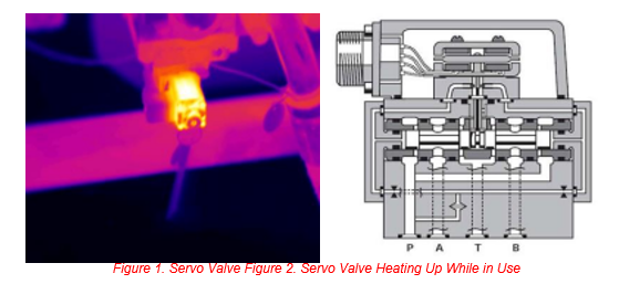
Servo valves have a maximum operating temperature, we have found the best method to prevent us from having unexpected failures due to temperature is to trend the operating temperatures in hopes of detecting when they begin to rise and responding on a scheduled basis.
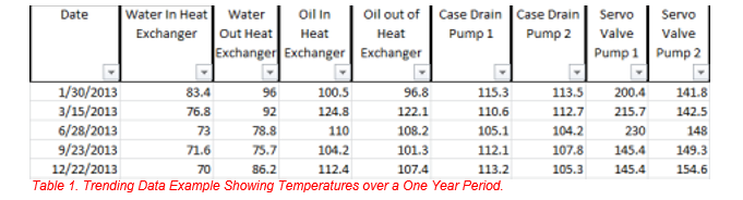
In Table 1 you can see that Servo Valve Pump 1 shows an upward trend in temperature that drops off in September due to being replaced. Also, Table 1 shows that we are trending the case drain lines as well as the water to oil heat exchanger.
ACCUMULATORS

Hydraulic system accumulators are used to supplement flow and are a valuable hydraulic system component. IR inspections are a quick way to scan the accumulators for proper operation. We have found that many times the accumulator’s nitrogen charge gage is broken or so discolored the gage is hard to read. We could simply feel of the accumulators by hand to see if they have a warm oil side and a cooler gas side but we have found the quickest and safest method is a quick IR scan. The IR scan can give a clear image of what is going on with the accumulator. The bladder could be discharged or leaking and this information can be used to justify funding for repairs or replacement. We have even seen cases where accumulators were inadvertently valved out which the IR camera can detect as well. In this case we would make a note of it in the report so that the system engineer could confirm whether it needed to be opened or closed.
PROCESS AIR FLOW
Ensuring that your process air is being properly conditioned is a critical way to protect sensitive equipment within the flow path as well as reduce required run time needed to meet specified conditions. Reducing run time can be an excellent way to drastically reduce operation cost.
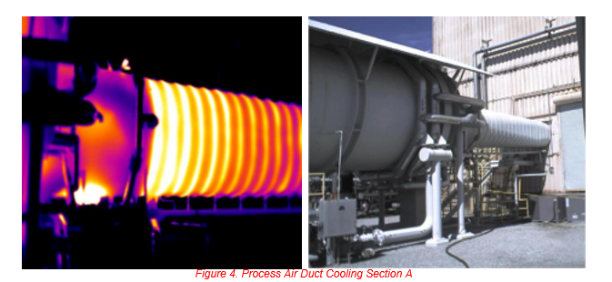
Figure 4 shows a cooling section of a Process Air Duct that is not getting enough cooling water flow. While cooling water flow is often monitored remotely, it is not practical to instrument every section or passage of the cooling system therefore it is possible that remote indicators appear normal when in fact large sections of ducting are not flowing enough. The doubled wall sections of duct are equipped with cooling passages all throughout. Our systems engineers are able to compare the water flow data through these passages in the control room recorded at the same time the images were taken to prove that while the control rooms are seeing the proper water flow rate and temperatures, they are in fact not cooling large sections of the ducting as efficiently. Replacing some of the supply and return lines has helped to improve the cooling efficiency of the hot gases flowing through the duct as well as extend the life of the ducting sections that were being heated excessively. More extensive maintenance is needed to improve the cooling efficiency further decreasing energy cost, allow original design specifications to be reached, and lowering the temperatures the upstream compressors are subjected to. To address this issue some options are being considered such as flushing out the passages with rust and crude, removing solvents, and replacing sections of the ducting. This section of ducting is much larger and more complicated than the images represent so unfortunately replacing the duct is too costly at this time.
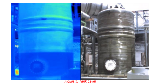
TANK LEVEL
In most cases fluid filled tanks will have a site glass or float type level indicator or possibly even a digital level gage that can be monitored from a control room or remote location. But many times the gage may need to be verified for accuracy. Another advantage of an IR inspection is that the tank level can be checked very quickly from a long distance with an IR camera.
SUMMARY
Expanding your infrared program with a mechanical emphasis can be a great way to increase system performance, reduce down time, repair cost, and operating cost. Showing real savings to asset owners is a good way to get their approval for additional periodic infrared inspections.
ACKNOWLEDGEMENTS
The author wishes to thank his management team and the complex leadership for allowing the opportunity to present these findings.
ABOUT THE AUTHOR
Dan is a Level II thermographer and has lead the ATA Infrared program for 5 years.
Related Articles
-
 Thermography Fundamentals
Know Your Subject Matter
Read the Story -
 Building Science
Three Ways the Pest Professional Can Use Infrared Thermography
Read the Story -
 Electrical/Mechanical
Positive IR Results In the Refining Industry
Read the Story