Looking Underground to Improve Reliability of Electrical Circuits
Looking Underground to Improve Reliability of Electrical Circuits
Stephen E Chad
National Grid
ABSTRACT
The underground infrastructure of electrical lines that supply power to homes and businesses in cities is ageing. Due to age and harsh underground conditions, failures do happen. It is expensive to replace these lines due to the planning, approval, digging, equipment, and manpower needed. Utilities are often penalized for the frequency and duration of power outages. Infrared is a valuable tool in identifying and repairing problems before they become outages.
INTRODUCTION
Before entering a manhole and performing an underground survey, it is important to have safety procedures and concerns addressed which include personal protection equipment, atmosphere monitoring, and enclosed space rescue devices.
Infrared inspections include underground cables, joints, transformers, and oil fused cutouts. Not to be overlooked are pad-mounted transformers, switchgear, and riser poles. In this type of environment, some things to consider are sun saturation, water level, and correct camera settings to deliver a clear and accurate image which leads to the repair of the equipment.
SAFETY
It is your personal responsibility not to do the work if it cannot be done safely. All inspectors should be trained in electrical hazard awareness, first aid / CPR, and manhole rescue / enclosed space. Safety begins before the job is started with a written job brief. This is a discussion of the hazards involved with the job and the controls used to minimize the risk of harm. A thorough job brief should include the following:
- Work Location – street address, manhole / pad number, nearest landmarks, and plans in place to activate emergency help.
- Job Description – the steps involved with the job and specialized equipment to be utilized.
- Energized Sources – what devices are at the site, their voltages, and steps taken to protect the workers from energized sources? Also review of the operations diagram of circuit.
- Personal Protective Equipment – This should include safety glasses, hard hat, harness, fire retardant clothing, electrical hazard-rated footwear, and high visibility vest. Also, other safe guards such as atmosphere monitoring and manhole rescue devices.
- Work Location Hazards – Locate the vehicles at a safe and acceptable job site. Consideration should be given for traffic / road conditions, manhole location, work area protection (barrier cones, signs), and the need for a police detail officer or flagger person.
After the appropriate procedures are reviewed and understood, the job brief should be signed by all involved, and posted in an accessible site for quick access. Should the scope of the work change due to weather, personnel change, or other reasons, it is important to stop the job and review the job brief again.
The safety of the workers, inspectors, and the general public is the utmost priority. It is important to set up a “zone of protection” when working around energized equipment and underground vaults. Whether you are working in the road at a manhole, or on switchgear in a parking lot, you must inform the public and employees of the change in conditions, and advise them on how to navigate around the work zone. This is done with the proper placement of signs, barricades, cones, and lights. Everyone is responsible for general public and crew safety.
ENCLOSED SPACES
Under normal conditions, an enclosed space does not contain a hazardous atmosphere; however, under abnormal conditions, a hazardous atmosphere may be present. An abnormal condition is an atmospheric condition that is immediately dangerous to life or can cause death. All work in enclosed spaces shall be performed in accordance with OSHA 1910.269 (e) standard utilizing all appropriate safe work methods. All appropriate Personal Protective Equipment shall be worn. The employee in charge shall conduct a written job brief before the start of each job covering any hazards or special precautions to be followed.
When work is performed in an enclosed space, the entrant shall wear a full body harness and be tethered to an approved rescue device by way of a rescue rope. The rescue ropes used in conjunction with the manhole rescue system are fire resistant. Ladders shall be used to enter and exit manholes or vaults.
An attendant is required for enclosed space entry. The attendant shall be trained in first aid, CPR, and manhole/vault rescue procedures. Before entrance into an enclosed space, a check for a hazardous atmosphere and for temperature or pressure differences that may present a hazard is required. Approved, calibrated instruments shall be used by trained employees prior to entry to test for oxygen deficiencies, carbon monoxide, hydrogen sulfide, and flammable gases. When the atmosphere has been tested safe and the cover has been removed, continuous monitoring shall be in use any time an employee is in an enclosed space. If at any time an unusual smell/sound is detected, the employee shall immediately exit the manhole until the source of the smell/sound can be identified and reentry deemed safe. Under no circumstances are employees to enter an enclosed space while it contains a hazardous atmosphere. If flammable gases or vapors are detected or if an oxygen deficiency is found, forced air ventilation shall be used to maintain oxygen at a safe level and to prevent a hazardous concentration of flammable gases and vapors from accumulating.
INFRARED SURVEY OF MANHOLES
Manholes are typically located in large urban areas. To perform a thermal survey on every manhole location would not be cost-effective or practical even though cameras have come down in price and are far more portable than before. However, if scheduled or emergency work is being done anyway, it is beneficial to scan with the infrared camera or heat gun as well. When scanning specific underground feeders, consideration should be given to reliability performance, voltage sensitive customers, and system load. Other factors include manholes with multiple circuits and devices, and proximity to the source substation.
Important Tips:
- Before entering the manhole with your personal protective equipment on, it is important to have the IR camera attached to you by a wrist or neck strap to prevent the camera from falling.
- Have the IR camera ready when the manhole cover is opened. The ambient light and solar heating will create the appearance of a hot spot on the cable. This can be defused by using your body or some type of tarp as a shade.
- Take advantage of scanning what you can from the outside. Some manholes are small and there might not be a need to enter.
- The IR camera cannot see through water. The manhole needs to be pumped to a level below the lowest conductor or device.
- When taking the digital and infrared image, it is better to get a wider angle view than a close up. This will allow for the concern to be easily identified and repaired.
- The atmospheric conditions in the manhole are different than outside. Adjust the camera temperature, humidity, and distance settings accordingly.
- Use external light in the manhole when taking digital photos for better results. This can be a strong flashlight or a drop lamp.
- When surveying a manhole, document any concerns with clear images including circuit numbers, phasing, and any other identifying information available. Then, get out. You are entering an area that has not been disturbed for a long time. Changes in water level and other outside forces may cause concern.
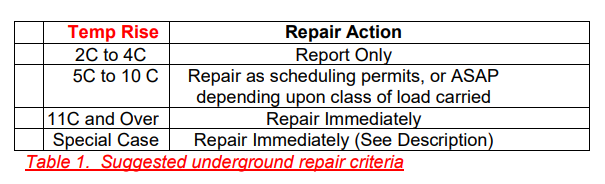
In the underground environment, most cables and equipment are wrapped with arc proofing material or insulated heavily to prevent flash-over if a fault does occur. Because of this, most readings are of the covering rather than the actual component which is the conductor or switch itself. An infrared camera’s ability to detect a defect depends on the construction of the device, the material used, and the amount of current flow. Table 1 illustrates the suggested repair criteria for underground components. This is only a guideline as other factors will weigh on the repair of the device.
Below are some examples of concerns found while inspecting underground electrical equipment.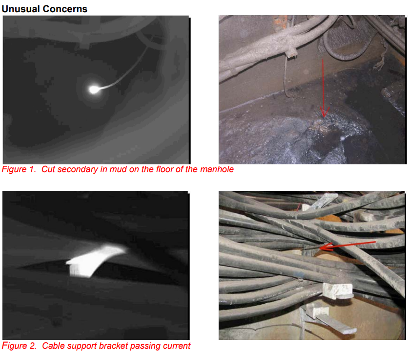
When performing an underground infrared survey, it is important to expect the unexpected. Figure 1 shows a severed streetlight secondary buried in mud on the manhole floor. The conductor was energized, and not properly insulated. Figure 2 reveals a cable support bracket that could be carrying current due to the chafing of the conductor resting on it. These could be potential faults, but are also safety concerns to the technician and crews working in the manhole.
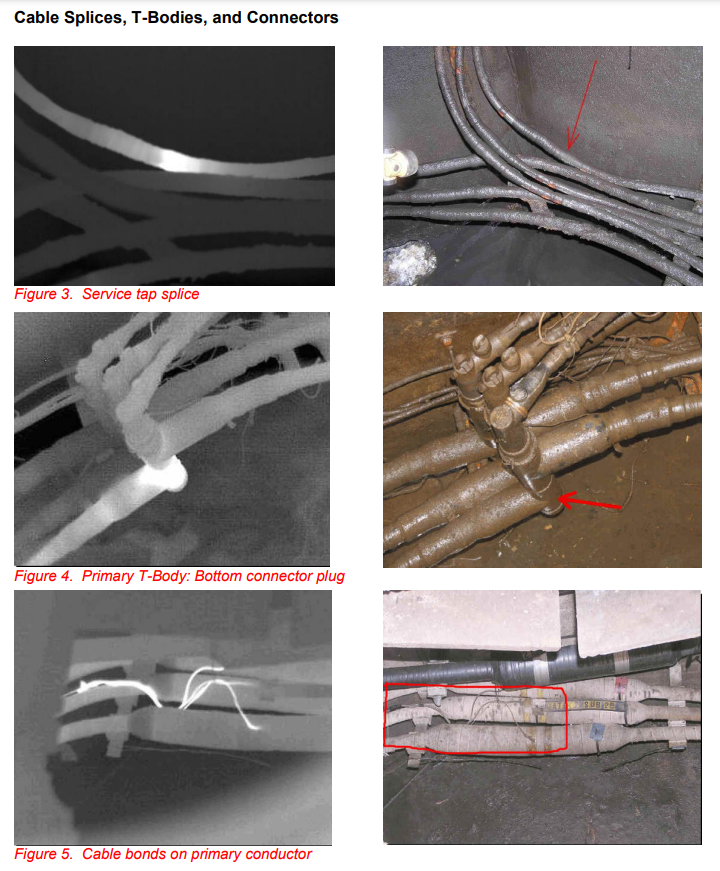
The installation of splices on HV networks requires a high level of competence and quality control. Very small errors during installation may result in future joint failure. Some common connector installation problems are not inserting the conductor fully into the connector, improper cleaning of the conductor, using the wrong compression tool, and applying the wrong amount of inhibitor. The result is that over time, the connection will start electrical arcing, and heat up. This will cause the insulation to break down, and allow contaminates like water, oil, and dirt in. This will cause the connection to fail. Infrared is a valuable tool in finding these potential failures in a non-destructive manner.
Figure 3 shows a splice used to join two conductors together. Figure 4 is of a T-Body Connector which can be connected with other cables to make a branch circuit. Both are common splice and plug type connectors used in manhole applications. Figure 5 is an image of defective bonds used in cable grounding for safety and reliability purposes.
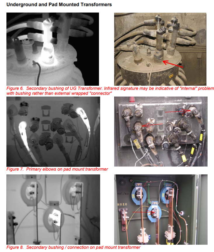
Transformers used in the underground environment can be located in a vault, or mounted in a pad. In this application, the purpose of a transformer is to step down the voltage to a useable level. Typical infrared inspections of transformers involve:
- Inspecting the outside casing for an even heat pattern within the working temperature rating of the transformer. Hot spots could indicate an inadequate oil level or internal problems. • If the transformer is equipped with radiator tubes, insure they are working properly. Cold tubes can be indicative of a blockage, or low oil level.
- Looking at primary and secondary bushing connections. Adjusting the level and span of the infrared camera can determine if there is an internal problem as in Figure 6, or an external bushing/connection concern illustrated in Figures 7 and 8.
An infrared inspection of transformers identifies faults not generally found during physical inspections.
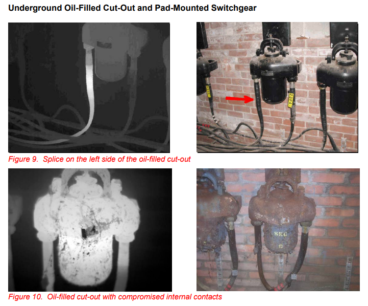
Manhole-mounted oil fuse cut-outs (OFC’s) and pad-mounted switchgear are devices that provide over current protection, sectionalizing, and load break operations in underground distribution systems. In some locations, there is a program to replace OFC’s with pad-mounted or submersible switchgear. This is due to harsh underground environment that subjects them to corrosion and unacceptable failure rates. Some common problems are connections as in Figure 9, and internal contact heating exemplified in Figure 10.
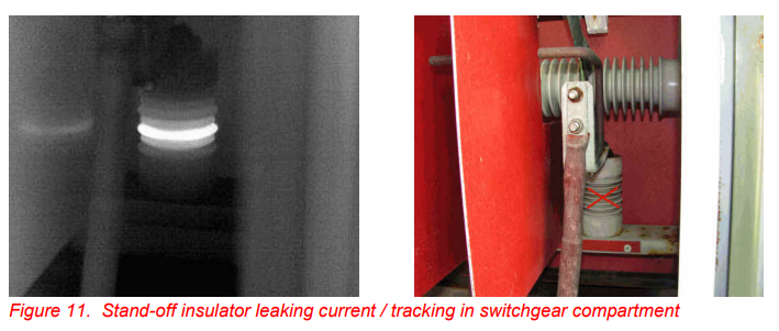
Insulators provide separation from ground and the voltage source. Faulty insulators as in Figure 11, located in pad-mounted switchgear, can cause an outage. The insulator may have external contamination by oil and dirt, or it could be cracked.
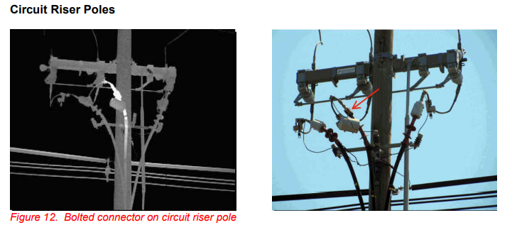
A through underground infrared inspection would not be complete without examining the adjacent overhead apparatus including circuit riser poles, switches, lightning arrestors, and conductors. In Figure 12, the bolted connector on the circuit riser pole cable termination was defective. The absolute temperature was 313°C which caused the animal protection guard around the connector to melt.
SUMMARY
-
Using infrared technology in the underground environment can reveal problems with electrical equipment before unscheduled outages or equipment damage occurs. It is important to follow safety and enclosed space procedures during these surveys as these are frequently hazardous inspection environments.
REFERENCES
-
- National Grid Standards Work Methods Bulletin #09-05 “Safety Precautions for Enclosed Space” 2. National Grid Standards Work Methods Bulletin #09-14 “Zone of Protection” 3. National Grid Electric Operating Procedure # NG-EOP UG001 “Infrared Non-Contact Thermometer Inspection Requirements for Underground Inspection”
- National Grid Training Center presentations on Enclosed Space and Underground Electrical Maintenance
- United States Department of Labor OSHA Standard 1910
ACKNOWLEDGEMENTS
The author wishes to thank Peter Bruder and Michael McCormick of the National Grid Engineering Laboratory for providing their experiences and resources to make this work possible.
ABOUT THE AUTHOR
Stephen Chad is a Level II Certified Thermographer for National Grid with 11 years of experience with infrared. National Grid is the largest electrical utility company in New England. The Engineering Laboratory performs infrared surveys on over 400 substations, 350 distribution circuits, and all transmission circuits on an annual basis. Stephen holds a Bachelors degree in Electrical Engineering Technology from Wentworth Institute of Technology and a Masters Degree in Business from Anna Maria College.