Factors Affecting Accurate Furnace Thermography
InfraMation 2015 Application Paper Submission
Andy Whitcher
Tecpinions Ltd
ABSTRACT
Accurate temperature measurement of tubes inside a fired furnace is extremely difficult. It requires good understanding of thermal, physical, process and operational factors inside the furnace firebox. This paper seeks to analyze some of these factors to help you to improve the accuracy of your furnace tube temperature measurements.
INTRODUCTION
Why do we want to use thermography for furnace tube temperature measurement? If furnace thermography is difficult then surely there must be a simpler, perhaps cheaper, method for monitoring the condition of the furnace tubes? The answer to this question is that yes there are cheaper and simpler methods for monitoring tube condition but they only allow the furnace owner/operator to assess the condition of very small parts of the furnace. They are also unreliable and are more reactive than proactive. In the world of furnace operation, reactive condition management might mean large scale emergency incident management!
Furnace thermography, whilst difficult to perform accurately, allows us to monitor the condition of almost the entire inside surface of the furnace. We can carry out both qualitative and quantitative monitoring of the furnace components; looking at the temperature distribution over components as well as measuring their temperature inside the furnace firebox. It can be used proactively, even to predict the condition of the furnace into the future allowing the owner/operator of the equipment to plan interventions before unpleasant things happen.
The owner/operator of a process furnace faces two challenges. Firstly they must maximise the efficiency of the furnace in order to maximise profit. Secondly they must maintain the mechanical integrity of the furnace to maintain reliability, ensuring that the furnace continues to operate and meet the first objective.
Furnaces have many different components but the key to safe operation is the condition of the furnace tube. This is the pressure containing envelope. If it fails, the consequences are dire. The resulting incident can destroy the furnace and other process equipment around it and can result in loss of life. Most furnace tubes are metallic and have a maximum operating temperature which is based on the properties of the tube metal and the pressure contained within the tube. Monitoring this temperature and ensuring it does not exceed its maximum operating temperature will ensure the furnace operates safely.
CAMERA SELECTION
So we have decided that we will use thermography to monitor the temperature of the surface of the tubes in the furnace but which camera should we choose? There are many available but not all of them are suitable for this job. Thankfully, radiation science will steer our choice of camera to the most suitable one. We know from our level one training that the radiation emitted from an object will increase with its temperature. For a real body, the total power emitted by an object over all wavelengths is given by the Stefan-Boltzmann equation:

In level 2, we examine this further and discover that the radiation intensity from an object is not constant at all wavelengths. There is a mathematical relationship between radiation intensity and wavelength. This relationship was discovered by Max Planck and the equation that describes this relationship carries his name:

This daunting equation is actually quite simple. There are only two variables in it, the rest are mathematical constants. If we choose a temperature (in Kelvin) and vary the wavelength we will obtain the variation in radiation intensity with wavelength for an object at that particular temperature. If we repeat this process for a number of different temperatures, we obtain a family of curves which look like this:
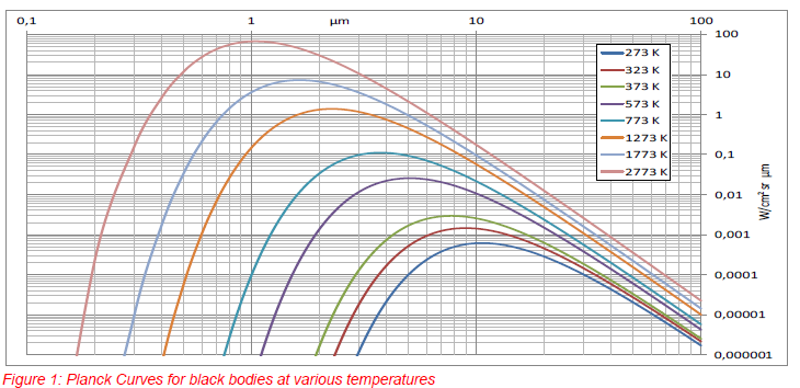
There is a clear deduction to be made from this family of curves. The peak of the radiation intensity shifts towards shorter wavelengths as the temperature of an object increases.
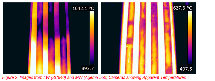
We can use cameras with two types of detectors; those that detect wavelengths between 2-5µm (Mid Wave) and those that detect wavelengths between 8-14µm (Long Wave). For high temperature targets, Mid Wave detectors will be better at imaging because there is more energy available in this wavelength and they can therefore provide a better image. This can easily be seen by comparing images from the same furnace using a Mid Wave (MW) and a Long Wave (LW) camera.
There is another reason for selecting a Mid Wave detector and this is because of the environment inside the furnace firebox. Between the camera and the furnace tube there are normally flames. The flame is the source of most of the energy in the lower part of the furnace. It is the region where the combustion reactions occur, converting stored energy in the fuel into heat. This energy is not related to the temperature of the tubes but it enters the camera and is measured by it. Fortunately for us, a well controlled natural gas flame has a fairly high transmission in a narrow band of wavelengths in the mid wave band.
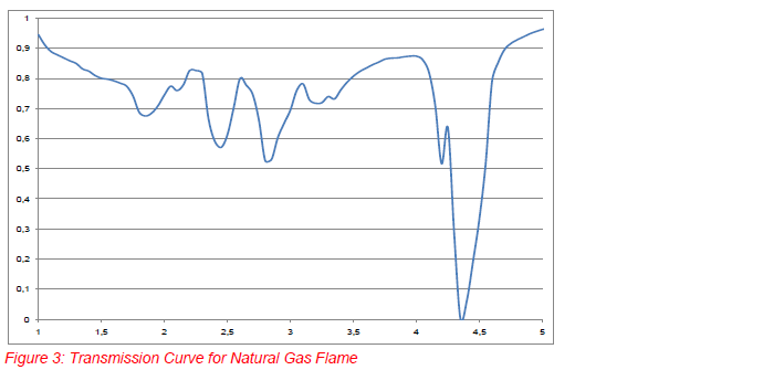
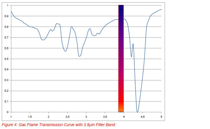
The flatter region of the curve around 3.5-4µm is the useful part. To take advantage of this, a filter is used with a waveband of about 3.75-4.2µm in cameras designed for furnace thermography. The center of this waveband (3.9µm) is the name given to this filter. So a Mid Wave detector fitted with a 3.9µm filter will eliminate most of the radiation from the flame whilst still receiving enough energy to give a good image.
EMISSIVITY
If we want to measure the temperature of an object accurately we must set the correct emissivity for the object in the camera. This is simple enough and in level 1 you are taught two methods from the ISO 18434-1 standard for measuring emissivity. Unfortunately neither of these methods is suitable for use in the furnace environment. We cannot use the reference method because the temperature inside the furnace is too high to use a piece of PVC tape. It would not be safe to reach in and stick it on and it would burn off instantly! The reference method is also unsuitable because if we use a thermocouple to measure the back side of a tube near an inspection window this will be a very different temperature to the front side because of direct radiant heating from the flame and cooling from the air being drawn into the inspection port.
The setting of an exact emissivity value is also complicated by the condition of the tube. The emissivity is usually not constant over the surface of the tube. It is always rough and covered in some sort of scale which is the products of corrosion or the combustion of the fuel. The emissivity is almost always high as this assists in the operation of the furnace. Emissivity and absorptivity are equal so the higher the emissivity of the tube, the more heat transfers into the process fluid inside it. Having a high emissivity also helps us by reducing the error in temperature measurement if we guess a value rather than measure it.
In practice we can either estimate one high value for the emissivity or we can perform two measurements at different emissivities on the same tube and report that the true temperature is between these two values.
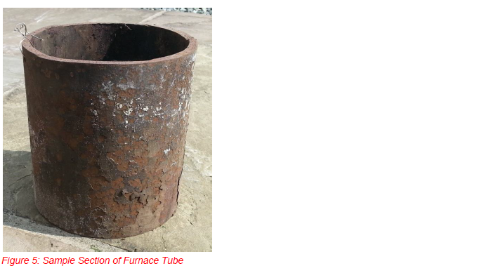
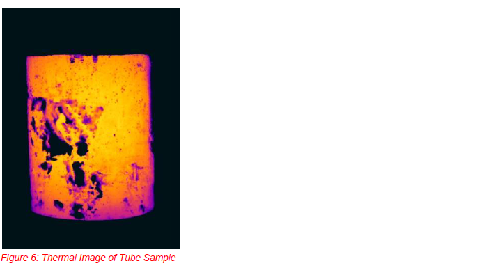
If we are lucky we can obtain samples of tubes like the one above and test them to determine their emissivity and then use that value for the furnace the sample came from. The test must be done at a temperature close to the normal operating temperature of the tube and can be done using the thermocouple method. The image below shows the tube sample after heating to around 500ºC in a pottery kiln. The temperature of the sample is almost uniform so the variation in apparent temperature tells us that the emissivity of the sample must be varying across its surface.
When determining an emissivity by this method and also when performing measurements in the field it is probably best to use an area or box measurement tool and take the average temperature in the box. This should help to cancel out the variation in emissivity inside the box. Using a spot tool may give a value that is too localized. We must also be careful to use a box measurement tool that only covers the central third of the tube or the emissivity value will start to be affected by the angle of observation.
REFLECTED APPARENT TEMPERATURE
This parameter plays a significant part in measurement inside a furnace. Errors in determining reflected apparent temperature (Trefl) can have a serious effect on measurement accuracy. The reason Trefl is so important is because our target object (the tube) is below the temperature of the surroundings.
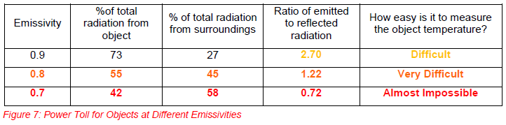
In level 2 we learn about power toll. Power toll tells us that we can assess the total radiation entering the camera to determine if our measurement will be easy or difficult. The furnace tube is an opaque object and opaque objects have two sources for exitant radiation; the amount emitted by the tube and the amount reflected off it from the surroundings. As an illustration, the table below shows a comparison of the percentage of the total radiation from a tube and the surroundings at three different temperatures. The temperature of the tube is assumed to be 600 ºC and the temperature of the surroundings 900ºC. In order for us to obtain a good measurement the rule of thumb is that the radiation from the object should be about five times the radiation from the surroundings.
When we set an incorrect Trefl in the camera and assume an emissivity we are actually compounding our errors. Setting the wrong emissivity makes the camera calculate an incorrect reflectivity. It then uses the incorrect reflectivity combined with an incorrect setting of Trefl to determine the amount of radiation it must subtract from the total it has detected to account for the effects of reflection. This is before it corrects the remaining amount of radiation for the effect of emissivity and then determines the temperature of the object from its calibration curve.
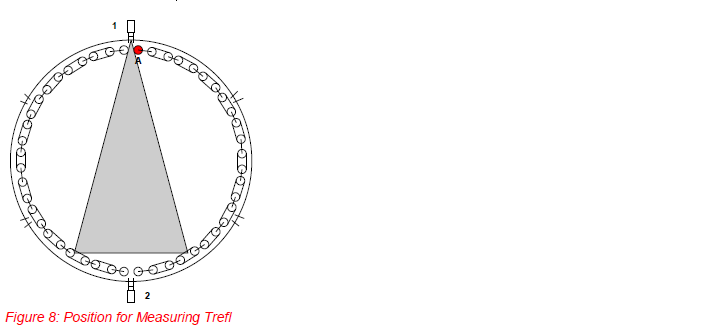
We must always be careful to measure a Trefl that is valid for the location of the tube we wish to measure. The objects reflecting off the target are the tubes and wall opposite it. We must therefore measure an average apparent temperature of this region of the furnace by first looking through an inspection port next to our target and setting it in the camera before moving to a position to look at the target. In the figure below, we first stand at position 1 to measure Trefl before moving to position 2 to measure tube ‘A’ (in red).
FURNACE OPERATION
The last factor we will examine in this paper is the effect of the furnace operation. In order to perform at maximum efficiency the correct mix of fuel and air must be burnt. In this paper we will only discuss gas fired burners. When a furnace burns oil as the fuel there are soot particles burning in the flame and steam required to atomize the fuel which release energy that cannot be filtered out with a 3.9µm filter.
As we saw earlier, a well-controlled natural gas flame has an infrared absorption spectrum that has a region of high transmissivity where we can use a filter to eliminate the effects of radiation from the flame. Unfortunately not all furnaces are operated well and we rarely see a flame like the perfect one used for the selection of the 3.9µm filter. In reality the line seen in figure 4 is constantly moving as the composition of the gas and the flow rates of air and gas change. The transmissivity of the flame in the narrow band width of the filter is moving up and down. Well-tuned burners will give higher transmissivity and poorly tuned burners will give lower transmissivity.
When the transmissivity of the flame drops it becomes more and more visible to the camera, adding to the energy that the camera detects but the camera is unable to differentiate between the energy that comes from the tube and the energy coming from the flame. There is no object parameter setting for us to compensate for this and our measurement accuracy will drop dramatically. The thermal situation is illustrated in figure 9.
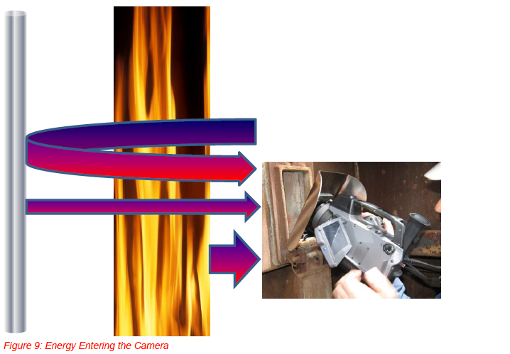
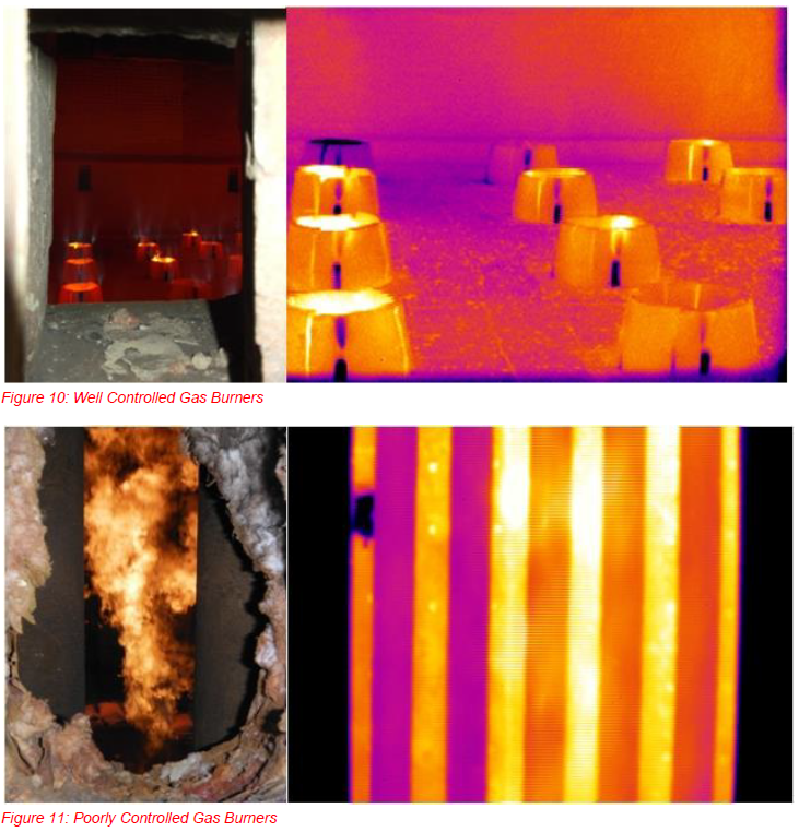
In figure 10, below, we can see that the burner flame pattern looks good and the flames are completely invisible to the camera whereas in figure 11 the burner is poorly adjusted and the flame is clearly visible to the camera.
Of course, the operation of the furnace is normally out of our control. We have to provide the owner/operator with good quality images and analysis but if we see that the burner control is poor we can include this information in our reports to alert the owner/operator of the furnace that the results we have given may not be the full story. Usually customers are quite receptive to ‘advice’ from thermographers provided it is offered in a constructive manner. They will often make efforts to tune the burner operation during a survey so that they receive the maximum benefit from it.
If the burner operation is not improved to get better results and we have to use images like the one in figure 11 then we must be sure to make measurements away from the areas of the image where we see the extra energy from the flame to improve our accuracy.
SUMMARY
There are many factors that affect the accuracy of furnace tube temperature measurement. To do a good job we must understand what the factors are, how significant they are and what we can do to compensate for them. All of this can be achieved by good training and practical experience.
REFERENCES
Cronholm, M.;” Thermodynamics of Furnace Tubes – Killing Popular Myths about Furnace Tube Temperature Measurement”; Proc. Inframation 2009
Infrared Training Centre; “Level 2 Thermography Course Manual (Eurasia)”; Chapter 5 pp 34-40; ITC 2014
Infrared Training Centre “Thermography for Furnace Applications”; ITC & Petroval 2011
ISO 18434-1, Condition Monitoring and Diagnostics of Machines, Thermography, Part 1: General Procedures
AUTHOR BIO
Andy Whitcher is a keen sailor competing at national level within the UK. When he is not sailing, he is the director of Tecpinions ltd, a UK based thermographic consultancy. He holds an honours degree in Chemical Engineering and is a Chartered Chemical Engineer Andy has 24 years experience in the oil industry as a Process Engineer, Inspection Engineer and Thermographer. He holds a BINDT Level 3 in Thermography including all three specialist application qualifications. Andy is also a Licensed Instructor with ITC teaching Level 1, Level 2 and Gas Detection Courses
Related Articles
-
 Electrical/Mechanical
Mechanical Applications for Industrial Infrared
Read the Story -
 Electrical/Mechanical
Extending gear life on SAG Mills, Ball Mills and Kilns using Thermal imaging techniques
Read the Story -
 Electrical/Mechanical
Interesting IR Opportunities Found Over 14 years as a Distribution Line and Substation Thermographer
Read the Story