Identifying Gear Alignment and Lubrication Concerns
InfraMation Application Paper Submission
Randy Sheppard
Lube Expert - Shell Lubricants – Canada
ABSTRACT
Gears are critical, costly components to many pieces of mining and industrial equipment. When properly aligned and lubricated, we can increase efficiency, as well as increase gear life exponentially. Failures with regards to any gear set are very costly and exposes technicians to very hazardous conditions. What do we look for? What does temperature tell us about lubricant? What does temperature tell us about alignment? What does temperature tell us about the other rotating components such as support bearings?
INTRODUCTION
Gear IR inspections give a great indication of what to look for during detailed shut down inspections.It is a very quick process, when performed routinely and can indicate two key factors of gear performance; gear alignment, as well as lubricant coverage and performance. Over a period of time, periodic IR inspections can identify any developing patterns in the gearing. In a perfect world we like to see a narrow, even temperature pattern across the gear. A gradient in the gear set can be a result of increased surface load/contact due to under lubrication leaving the gears partially exposed, or improperly aligned gears reducing surface contact.
Gears 101: There are multiple failure modes and causes for any gear. During a shutdown inspection we want to identify surface condition indicators, failure modes we look for include:
1. Adhesion – this is localized welding as a result of insufficient lube film thickness. This can be a result of what we call boundary lubrication, when the lubricant film is too thin and does not keep adequate separation between the contact surfaces. Many lubricants are additized to support this, however under-lubrication can result in this phenomena.
2. Abrasion – Abrasive wear is a result of particles in the operating zone of the gears. We can identify abrasion in two categories, two body abrasion, when there is a loss of profile in the gear itself resulting in scratching of the gear face. The second is three body abrasion when there is a foreign particle introduced, such as sand, metal particle, other sources depending on the operating environment.
3. Plastic deformation – plastic deformation is a typically a result of overloaded operating conditions. This will lead to permanent change of profile, changing the contact surface of the gear teeth.
4. Pitting - Pitting occurs when fatigue cracks are initiated on the tooth surface or just below the surface. Usually pits are the result of surface cracks caused by metal-to-metal contact of asperities or defects due to low lubricant film thickness.
5. Spalling - a large or massive area where surface material has broken away from the tooth. This is often a result of progressive pitting.
6. Miscellaneous – There are many more concerns and wear modes that may be addressed, however for the purpose of this report it has been limited to the previously mentioned methods. Some other items to look for include, indentations, transfer of impressions, and manufacturing defects.
There are many gear applications in many industries around the globe, some examples of what we are discussing here today include:
1. Electric mining shovels
2. Large mills, and kilns
3. Drag Lines


Using thermal imaging to inspect operational gears helps identify where we have to look during shut down inspections. If we are seeing a temperature gradient from end to end, we know to at least start with one of two things, gear alignment or uneven lubrication. When shut down, if we observe an uneven wear pattern it typically means misalignment. On the other hand, if we see adhesion, it is a strong indication of under lubrication or lubricant breakdown.
If we identify any hot spots, or anomalies, it is a good indication of abrasive wear, or uneven lubricant application. As a result of abrasive wear, the contact surface will be altered from the loss of tooth face profile resulting in uneven wear/temperature patterns. If there is an issue with the application of lubricant, there may be areas with less lubrication fill, resulting in tighter tolerance, and higher temperatures.
THERMAL GEAR INSPECTION
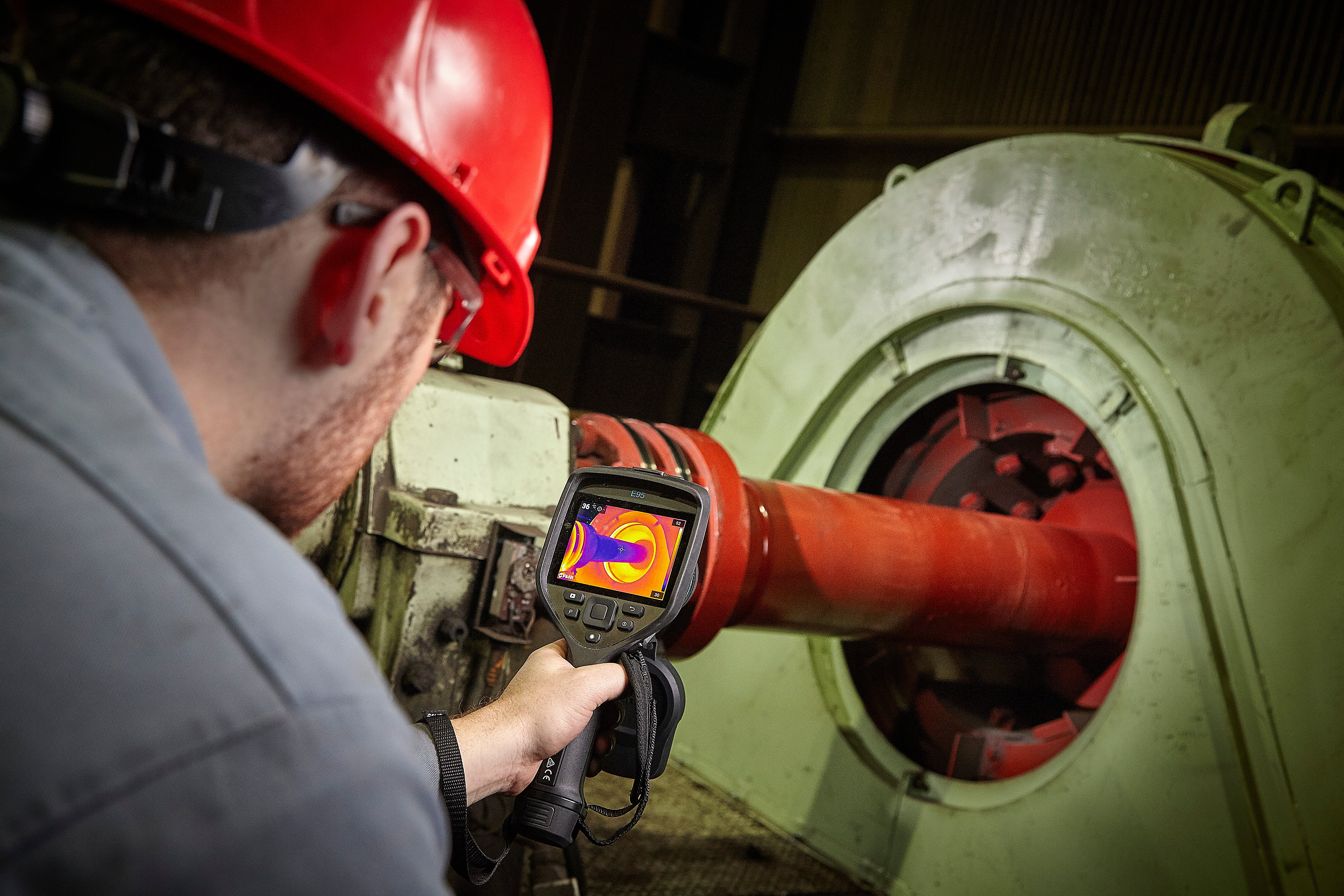
Figure 4 is the IR image of the hoist bull gear of a BE 495 electric shovel. The running IR inspection indicated desirable alignment and lubricant coverage/performance as there is a modest 1⁰C temperature gradient. At this point we would be pleased with the result and recommend continued IR inspections and lubricant coverage

When performing these inspections, we look for consistency, a flat, even temperature across the tooth face is desirable. Although AGMA has a published standard allowing up to 12⁰C range, we like to follow a more stringent guideline of 8⁰C. Although this range may seem very low, it allows for corrections to be made much earlier in detrimental conditions. Operating a gear with poor lubrication will typically result in metal to metal contact in the affected areas, leading to failure modes such as adhesion, abrasion, as well as added stress from higher temperatures. The lack of lubricant will allow for a thinner lubrication regime, promoting adhesion, which essentially is micro welding of the gear face, which then creates wear material in the gear case potentially leading to abrasive wear.
On the other hand, if we identify a temperature gradient attributed to misalignment, it can cause extreme stress to uneven segments of the gear. If we have less than 85% tooth face contact, we typically see an uneven wear pattern in the gear. This causes unwanted stress to the indicated side of misalignment. For example, if we have a higher load on the drive end of a pinion, we will see premature, excessive loss of tooth profile in the indicated area. This in turn will create an environment accommodating three body abrasion, as well as shortened gear life due to the excessive stress over a smaller load area. In time this will typically lead to overload conditions, including cracking, rippling, as well as plastic deformation.

During an inspection of a fertilizer granulator, the above photos show a severe trend from left to right. From end to end there was a delta of 23.6⁰F/13.1⁰C, which was determined to be uneven/under lubrication as shown. This can cause issues such as, uneven wear trends, and adhesion.

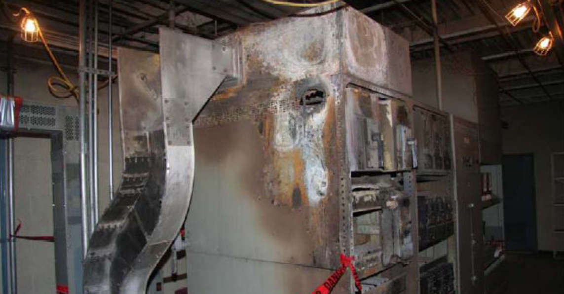
The image shown in Figure 6 shows severe pitting, which is often a result of poor lubrication, showing increased, uneven temperature during thermal inspections. While performing thermal inspections of a gear set, it is a good practice to observe the associated bearings as well. This may be an indication of any identified alignment concerns. Bearing installation and orientation will have a direct influence on gear operation and performance. With Thermal imaging of a bearing, anomalies may be identified, such as hot spots, increased temperature, or temperature spikes.

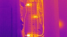
Figure 7 and 8 show a concerning temperature pattern which was observed on a sag mill. During a shutdown inspection concerns with the pedestal were identified. This in turn was causing alignment issues, causing uneven wear of the gears. After corrections were made temperature spikes were observed as a result of high spots on the gear. The drive pinion has since been replaced, however now there is a new concern as the girth gear has a wear pattern which is being transferred to the new pinion, this will result in accelerated wear and shortened service life of the gear.
SUMMARY
When using Thermal Imaging to trouble shoot gear concerns, it is important to keep in mind it is primarily an indicator. When a temperature trend is identified it requires further attention to pinpoint the root cause, and method of repair. It is a very cost effective, efficient method to aid in the maintenance of gear components, while assisting in gear life extension.
REFERENCES
ANSI/AGMA 1010-E95
Appearance of Gear Teeth - Terminology of Wear and Failure
ANSI/AGMA 9005-E02
Revision of - ANSI/AGMA 9005--D94
AGMA 912--A04
Mechanisms of Gear Tooth Failures
ACKNOWLEDGEMENTS
The authors wish to thank the Infrared Training Center at FLIR Systems and NA Shell Lubricants for making this work possible.
ABOUT THE AUTHOR
Randy is a Level I thermographer and has worked in the heavy mining industry for 10 years.
Related Articles
-
 Thermography Fundamentals
Know Your Subject Matter
Read the Story -
 Electrical/Mechanical
Five Years of Infrared Results at CNA – March 2005 through June 2010
Read the Story -
 Electrical/Mechanical
Maximizing the Return on your Infrared Electrical Inspection Investment
Read the Story