Techniques for Identifying Problems in Transformers
InfraMation 2012 Application Paper Submission
Saira Dar
3i Condition Monitoring Consultancy, LTD
ABSTRACT
You have found a hot spot on a transformer casing during a planned quarterly thermography inspection, but what does it mean? Is it a fault? If so, how bad is it? Does it require immediate repair? What is that hot spot actually telling you? This paper talks you through transformer basics: primary function, internal components, problem causes, and best test methods for fault identification. We are going to look at a real-life case study that highlights the importance of including thermography as a test method.
INTRODUCTION
Transformers are essential, and when they go wrong, they usually take out a lot of equipment. Quite often, a transformer problem can result in a complete loss of power to the whole site, a worst case scenario. A number of testing methods can be integrated into condition checks. This paper presents them in detail, highlighting the relevance of each in relation to the amount of information they can provide. The case study included in this paper discusses the importance of including thermography as a primary inspection tool.
A BASIC GUIDE TO TRANSFORMERS
Put in simple terms (not intended to offend anybody), a transformer basically steps-up or steps-down alternating current. Alternating current enters and goes through a coiled wire; the number of turns in the coil will determine the ratio. The alternating current passes through a magnetic field to produce electricity. This formula expresses the simplicity of the setup:
Voltage (secondary)/Voltage (primary) = Number of turns (secondary)/Number of turns (primary)
In other words, we have 2 coils of wire stuck next to each other and it is the ratio between them that determines the output.
A BIT OF TRANSFORMER HISTORY
The theory of electromagnetic induction, set forth by Michael Faraday in 1831, made the invention of the transformer possible. However, it was not until 1836 that the first device (an induction coil) was created. William Stanley, designer of the first commercial model, introduced the term ‘transformer’ in 1885. The first type of transformer to see wide use was the induction coil, which relied upon vibrating electrical contacts that regularly interrupted the current in the primary to create the flux changes necessary for induction.
Transformers vary in size, from a thumbnail to huge units weighing hundreds of tons, which are used to interconnect portions of power grids. All transformers, however, operate on the same principle. A few of the many types of transformers include: laminated core, toroidal, autotransformer, variac, induction regulator, stray field, polyphase, resonant, constant voltage, ferrite core, planar, oil cooled, cast resin, isolating transformer and many more!
I AM GOING TO CONCENTRATE ON…OIL-FILLED TRANSFORMERS!
For large transformers used in power distribution or electrical substations, the core and coils of the transformer are immersed in oil whose primary job is to cool and insulate. The oil circulates through ducts in the coil and around the coil and core assembly by convection. The oil is cooled by the outside of the tank in small ratings, but in larger ratings, an air-cooled radiator is needed. Where a higher rating is required or where the transformer is located in a building or underground, oil pumps are utilized to circulate the oil. An oil to-water heat exchanger may also be used.
Oil-filled transformers with a conservator (an oil tank above the transformer) may have a gas detector relay located on them called a Buchholz relay. These safety devices detect the build-up of gases inside the transformer, which could be the result of corona discharge, overheating or an internal electric arc. With a slow accumulation of gas or rapid pressure rise, these devices can trip a protective circuit breaker and remove power from the transformer. Transformers without conservators are usually equipped with sudden pressure relays.
The flash point (min) and pour point (max) of the oil used in transformers is 140 degrees C and -6 degrees C respectively. The dielectric strength of new untreated oil is 12 MV/m (RMS) and after treatment should be >24 MV/m (RMS).
WHAT DOES THIS ACTUALLY MEAN?
Transformer oils are subject to electrical and mechanical stresses while a transformer is in operation. In addition, there is contamination caused by chemical interactions with windings and other solid insulation (catalyzed by high temperatures). The original properties of transformer oil change gradually and it slowly becomes ineffective for its intended purpose after many years. Oil needs to be periodically tested to ascertain its basic electrical properties, to make sure it is suitable for further use, and to establish the need for maintenance activities such as filtration/regeneration.
These tests can be broken down as follows:
1. DGA (Dissolved gas analysis), which is recommended annually.
2. FA (Furan Analysis), which is every 2 years.
3. PCB Analysis, which is recommended annually. (Note: The use of PCB is now banned in the EU.) ∙ General electrical and physical tests, which are recommended bi-annually.
The Furan and DGA tests are not to determine the quality of the oil, but serve to determine abnormalities associated with the internal windings. DGA is used to determine the concentration and relative ratios one to another. This test is also used to diagnose operational problems with the transformer which may be associated with a physical change in the chemical properties of the insulating oil. For example, high levels of carbon monoxide, relative to other gases, may indicate thermal breakdown of cellulose paper. Or, another example, the presence of hydrogen in conjunction with methane may indicate a corona discharge within the transformer. Furan analysis is a measure of the degradation of the insulating paper. When the paper ages, its degree of polymerization is reduced, which means its mechanical strength also decreases. The degree of polymerization can be directly related to the concentration of furan derivatives in the oil. This test, therefore, is a direct measure of the insulation.
DON’T FORGET THE TAP CHAMBER!
A tap chamber (aka, tap changer or load tap changer) is a device fitted to the transformer for regulation of the output voltage to required levels. Tap chambers possess two fundamental features: ∙ Some form of impedance is present to prevent short circuiting of the tapped section. ∙ A duplicate circuit is provided so that the load current can be carried by one circuit while switching is being carried out another.
WHAT ABOUT THE WINDINGS?
Winding temperature can cause you problems, so let’s take a look at how the heat is generated. Heat is generated in a power transformer by current flow in the primary and secondary windings. At low loads, the quantity of heat produced will be small, but as the load increases, the amount of heat starts to become significant.
At full load, the windings will be operating at or near their design temperature. A temperature of approximately 105°C is considered the normal maximum working value for large power transformers based on the assumed maximum ambient temperature of 40°C. Operation of the transformer above its rated voltage by even 10% can cause significant temperature rise. Over-voltage operation may be the result of tap chamber or voltage regulation problems. Operating at temperatures above design limits can lead to damage of the insulation, which will reduce the useful life of the insulation, which, of course, inevitably reduces the life of the transformer. A temperature rise of 8-10 degrees Celsius beyond the maximum working value (if sustained) can halve the life of the transformer!
Examples of large-cost transformer findings include:
1. Internal winding faults
2. Faulty load tap chambers
3. Failed windings accessories (loose coil clamping bolts, etc.)
HOW CAN WE GET MAXIMUM LIFE FROM OUR TRANSFORMERS?
A transformer gas relay can provide protection for a power transformer by detecting the build-up of gases within it and/or by reacting to a sudden pressure surge, which may be due to a major fault. The winding temperature of a power transformer can be monitored by a sensor to protect it from prolonged over-temperature operation. Differential protection techniques can be used to protect transformers and associated equipment from faults within different zones. A single current transformer and relay can be placed on the grounded neutral of a star winding to protect the transformer from ground faults.
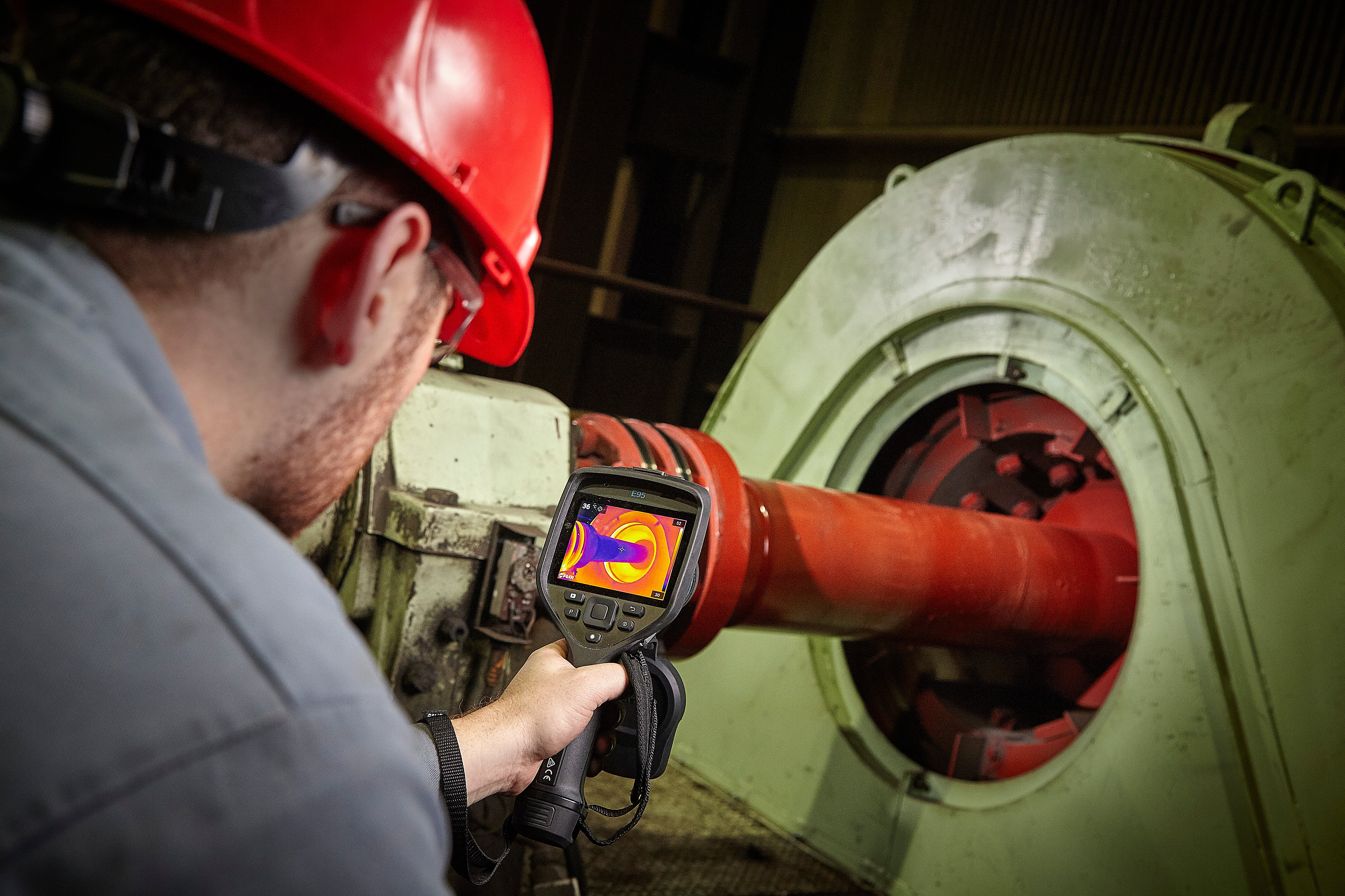
WHAT VALUE DOES THERMAL IMAGING PROVIDE?
I know I do not have to write an extensive list with regards to the benefits of thermography. I am sure you already know them, and if you don’t, then please read elsewhere! What I am going to share with you is a case study taken from a recent inspection I conducted. This case outlines the importance of the checks I completed, how thermography was a long shot at best, but the only tool I could have used for fault detection, and the results of my success story (and of course it had to be a success or I would not have wanted to share it with you!)
The first thing I would like you to do is completely disregard everything I have already presented! Why? All of the other methods of testing (oil, etc.) were not available for my transformer type. Whoever designed it overlooked the fitting of a drain tap—it is a completely sealed unit. (What sort of genius would do such a thing? I hear you asking!). So, although we cannot rely on oil testing (which would without a doubt give the most information), we do have voltage readings to use. However, the alarm system did not appear to be functioning... Unfortunately, everyone was oblivious to the events unraveling behind the scenes.
WALK WITH ME THROUGH MY DAY
On this particular site, there are 20 transformers, all with different ratings, different manufacturers, in different operating environments. (You can see what I am building up to here.) They all have a unique individual temperature profile.
The transformers were included within the routine thermography inspection, which also consisted of electrical and mechanical items. Baseline data had been collected and were continuously referred to along with alarm limits set for the size and classification of each unit. Two of the 20 transformers were sealed units with no drain points fitted. This fact made us keenly aware of the importance of the data collected from thermal imaging, performed at quarterly intervals, as one of the primary sources of test data on these units.
The key things we normally look at when checking the temperature profile of a transformer are the oil level, power cables, whether a uniform casing exists with no isolated hot spots, and whether the overall casing temperature is within classification limits for the ambient temperature during testing.
Figure 1 is a good example of a transformer showing both a normal oil level and casing temperatures that are within satisfactory limits. Note this transformer has a temperature gauge (Figure 2). It always is worth making a note of this temperature reading to ensure you are recording similar temperatures with your thermal imaging camera. Remember, double check your camera settings: emissivity, RAT (reflected apparent temperature), ambient temp, etc. If they are correct, then we can assume either the gauge is U/S, or that we are measuring a different spot temperature than where the sensor is located. These sensors should be set to an alarm temperature with a second alarm set to cut out the transformer once exceeded.


The rating on this problem transformer was 3,000 kVA (HV: 11,000, LV: 615) for a 3 phase, 50 Hz sealed unit with silicone insulation liquid. The temperature of the oil/liquid was 60°C and windings were at 65°C. The year of manufacture was 1997 (Merlin Gerin) and the total mass of the unit was 1,660 kg. The temperature alarm was set to 80°C. (Since I’d found a hot spot in excess of 100°C, this feature was clearly not functioning correctly!)
Obviously, I needed to report my findings immediately. I had already established the severity of the fault and knew it required immediate repair. Taking this step, however, meant shutting down the entire mill–not an easy task to convince people to undertake. I needed to get the facts to the big bosses who would ultimately have the authority to make the call.
Having recently purchased a FLIR T640 camera, along with an iPad I’d managed to convince our company accountant was absolutely necessary for my work, it dawned on me that I had the perfect tools to communicate my message efficiently and effectively. I quickly transferred the images from my camera into the FLIR Reporter™ App (an impressive piece of kit), generated a quick report, and emailed it to all of the senior managers within the mill, both to their email and mobile phone accounts. Without this technology, it would have been impossible to reach them all at the same time with such speed.
The beauty of thermography is that it is so visual. I knew it would be hard for anybody to see those images and walk away from the situation. And I was right—within hours, the machine was stopped. A specialist company was called in to remove the transformer’s top and the oil was drained.
Throughout the night, a team of people worked on the transformer to find the fault within the unit—arcing contacts within the tap chamber (Figure 8.)

As a result, power had been dipping throughout the day within the mill, but as the machines were reset, no one had made the connection between the outages and the transformer. The result of shorting contacts in the tap chamber is that you no longer have control of varying the voltage. (In most cases, this isn’t necessary, so the transformer isn’t affected during normal operation.)


Once the transformer was brought back on line, a recheck was conducted to ensure casing temperatures had returned to satisfactory limits (Figure 11).

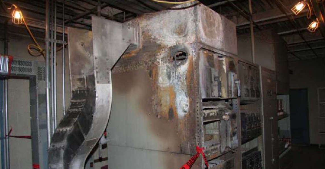
Within a 12-hour period, the transformer was back on-line and the mill was making money again! The identification of the fault, and the subsequent speedy repair prevented the unit from a catastrophic failure. The approximate cost of repair was £70.000. The approximate cost of catastrophic failure was estimated at a minimum of £250.000! As you can imagine, I went home that day feeling pretty good and wishing my fee was based on percentage of savings!
SUMMARY
Although transformers are often not included in routine thermography checks, the trending data thermography can provide is an extremely valuable diagnostic tool. Remember, you must have a thorough understanding of the machine in question in order to be able to establish what can potentially go wrong. You must also be aware of your limits. Thermography can identify many, but not all issues. It should never be the only tool in the box and should always be used in conjunction with other testing methods.
ACKNOWLEDGEMENTS
The author wishes to thank all the people at the mill who helped me with my quest to write this paper. (They all know who they are and have agreed to remain anonymous to spare me having to get permission to quote them, for which I applaud them!) I would also like to thank all the people who escort me around sites on a daily basis, listen to my stories, and share their stories with me. Without these gracious folks, I would not know half of the things I know today.
ABOUT THE AUTHOR
Saira is a Level III thermographer, training instructor, and company owner with extensive industrial knowledge and experience. She began her career as an electrical engineer and has been using thermal technology for the past 18 years. She is extremely passionate about what she does and is a keen advocate of training, development, and investment in people.
Related Articles
-
 Thermography Fundamentals
Know Your Subject Matter
Read the Story -
 Electrical/Mechanical
Five Years of Infrared Results at CNA – March 2005 through June 2010
Read the Story -
 Electrical/Mechanical
Identifying Gear Alignment and Lubrication Concerns
Read the Story