Use of Infrared Thermography in Krsko Nuclear Power Plant
InfraMation 2018 Application Paper Submission
Bojan Klavzar
Predictive Maintenance Lead Engineer
ABSTRACT
The purpose of this article is to present IR thermography as an effective predictive maintenance technique and to demonstrate the possibilities of its wide application in the energy sector. I would like to examine typical faults on the equipment at the plant, which were detected using several IR thermographic measurements over a longer period of time. At the Krsko Nuclear Power Plant (NEK), Slovenia, we have been using IR thermography as a predictive diagnostic method since 1992. NEK is equipped with a Westinghouse Pressurized Light Water Reactor of 2.000 MW thermal power. The power plant's net electrical power is 696 MW. It is connected to the 400 kV Power Line. The use of this non-destructive predictive technique contributes to greater reliability and availability of equipment, and indirectly to an increased fire safety. The article presents various practical examples of the IR Thermography application in the Nuclear Power Plant.
INTRODUCTION
In electric power systems, malfunctions are often reflected in local temperature rises. Local overheating can be due to increased contact resistance, friction, increased electrical load, induction, leakage of closing elements in pipelines, etc. In addition to local overheating, the absence of heating on elements such as capacitors, resistors, conductors and similar components, which may have to be heated to a certain temperature during normal operation, may also be a sign of an error. To detect such errors, we perform periodic thermographic inspections. Various examples of the use of IR thermography in Krsko Nuclear Power Plant are shown in the article.
TRANSFORMER TEMPERATURE RISE TEST
IR thermography is usually used at factory acceptance tests and site acceptance tests of new devices and at regular periodic inspections. The base line of a new device is very useful data for future trending. Figure 1 and Figure 2 show IR and visual image of the new 500 MVA transformer during the temperature rise test. The test load was 107% of the rated load. Every measured temperature was within the acceptance criteria.

115 KW AC MOTOR UPPER BEARING OVERHEATING
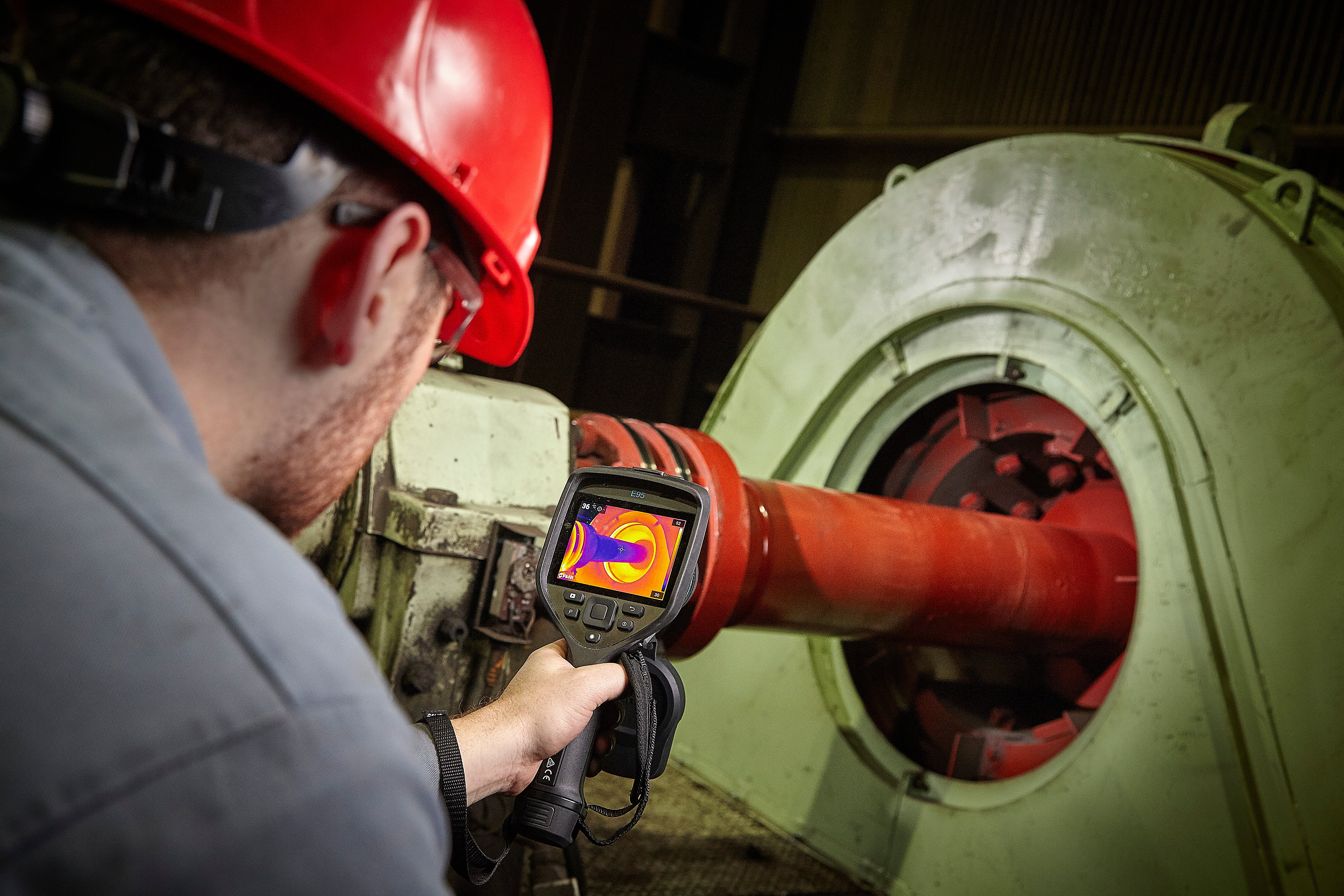
All rotating equipment generates heat at the friction-bearing points in the system – the bearings. Lubrication reduces friction and thereby reduces and to varying degrees dissipates the heat. Thermal imaging lets you literally “picture” this process while revealing the condition of bearings. When thermal images indicate an overheating bearing, you should generate a maintenance order to either replace the bearing or lubricate it. Figure 3 shows IR image of the 115 kW AC motor, where overheating in the motor upper bearing area was detected. The reason for overheating was a damaged upper bearing of the electric motor, which was replaced at the next scheduled maintenance.

GENERATOR LOAD BREAK SWITCH
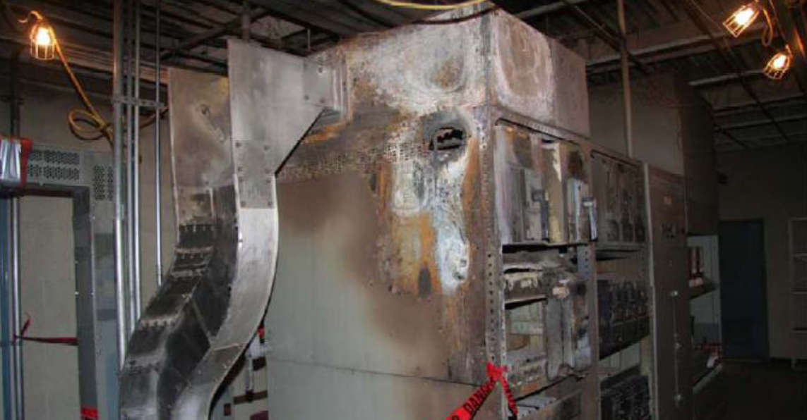
During the regular periodic thermographic inspection of a 21 kV main generator load break switch, a high temperature was measured at the connection between the generator circuit breaker housing and the enclosure of the bus duct. Figure 5 shows the IR image of the 21 kV generator load breaker switch, where overheating was detected. The measured high temperature on the housing, according to experience, is the result of a strong overheating inside the shielded collector. In the past, intense overheating at the identical site resulted in partial melting of the elastic bonding element. A request for corrective action on the component was issued. The error was corrected during the next scheduled outage. The cause of overheating was an inadequate fastened joint of flexible connections. Figure 6 shows the IR image recorded during the post maintenance test. The housing temperatures dropped to normal values.

We need to be very careful when analyzing thermograms at detected overheating on device housing. The reason for the increased temperature on the housing detected by the IR camera could be overheating on the body of the device itself or overheating inside the device. When the source of overheating is inside the device, the measured temperature on the housing of the device is usually lower than the actual temperature at the overheating source inside the device due to cooling to the environment.
DISCONNECT SWITCH OVERHEATING
During the thermographic inspection of the 400 kV switchyard, overheating at the disconnect switch on the transformer side was found. The over temperature of the connection between the disconnect switch and the bus on the transformer side (Figure 8, Ar1_a2-DV) was 25 K higher than the temperature of the connection between the disconnect switch and the bus on the power line side (Figure 7, Ar1_a2-ZB). Figure 7 and Figure 8 show IR images of the same disconnect switch. ΔT > 25 K is a sign of a serious failure according to the acceptance criteria. A request for corrective action on the component was issued. The cause of overheating was oxidized and corroded contact plates.

STEAM DUMP VALVE LEAKAGE
Figure 9 is the IR image of the main steam piping after the leaking STEAM DUMP valve. Figure 10 is the IR image of the main steam piping after the non-leaking STEAM DUMP valve. Absolute size of the leakage of a single valve is impossible to determine with IR thermography. A request for corrective action on the component was issued.

DEFECT ON THE HEATING DEVICE AND THE INITIAL STAGE OF OVERHEATING AT THE CIRCUIT BREAKER
During the periodic thermographic inspection of the circuit breaker (power supply for the three-phase ventilation heating device), the overheating in the initial stage at the circuit breaker connection in phase L3 (Figure 11, Ar3) was detected.

Electric current was measured due to the measured lower temperature on the conductor in phase L2 (Figure 11, Sp2) compared to phases L1 (Figure 11, Sp1) and L3 (Figure 11, Sp3). The measured electric current values were: IL1 = 25.95 A; IL2 = 0 A; IL3 = 26.06 A. The measured current values indicate incorrect operation of the heaters in the ventilation heating unit. This case is a good illustration that sometimes a very small temperature difference can be a sign of a serious failure. A request for corrective action on the component was issued.
OVERHEATINGS DUE TO EDDY CURRENT
Eddy currents (also called Foucault currents) are loops of electrical current induced within conductors by a changing magnetic field in the conductor, due to Faraday’s law of induction. Eddy currents flow in closed loops within conductors, in planes perpendicular to the magnetic field. They can be induced within nearby stationary conductors by a time-varying magnetic field created by an AC electromagnet or transformer, for example, or by relative motion between a magnet and a nearby conductor. The magnitude of the current in a given loop is proportional to the strength of the magnetic field, the area of the loop, and the rate of change of flux, and inversely proportional to the resistivity of the material. By Lenz’s law, an eddy current creates a magnetic field that opposes the magnetic field that created it, and thus eddy currents react back on the source of the magnetic field. For example, a nearby conductive surface will exert a drag force on a moving magnet that opposes its motion, due to eddy currents induced in the surface by the moving magnetic field. The current flowing through the resistance of the conductor also dissipates energy as heat in the material [1].

Figure 15 shows overheating on the earthing link connection between transformer piping. The pipeline connects 500 MVA transformer tank and the oil conservator.

The cause of overheating was a poor connection because of paint between the washer and the nut. The overheating repair was carried out by cleaning the paint on the connecting surfaces, replacing the bolt and re-checking the tightness of the bolted connection.
GENERATOR STATOR CORE LOOP TEST
Generators are subject to high electrical, thermal and mechanical stresses. Continuous extreme thermomechanical stresses and thermal cycles can have a particularly severe impact on the stator core. A flux test is used to measure the condition of stator core insulation to detect possible local insulation damage. During magnetization, insulation failure can result in local hot spots between several sheets of the core. These hot spots can be detected and localized with thermal imaging [2]. Figure 17 shows hot spots on the generator stator core.

SUMMARY
At the Krsko Nuclear Power Plant, Slovenia, we have been using IR thermography as a predictive diagnostic method since 1992. The use of this non-destructive predictive technique contributes not only to greater reliability and availability of equipment, but indirectly also to the increased fire safety. The article focuses on different practical examples of the IR Thermography being applied in the Krsko Nuclear Power Plant over a longer period of time. Systematic surveillance and expertise in diagnostic methods contribute to early detection of faults, inappropriate operating conditions and they help the plant assess the quality of maintenance activities. It is crucial for quality measurements and error detection to master the diagnostic method itself and successfully manage the measuring equipment, the production process as well as the related equipment. Moreover, regular monitoring of the results of preliminary measurements on the same components, operating experience and errors is essential also for root cause analysis of problems.
REFERENCES
[1] Princeton University – Eddy Current (https://www.princeton.edu/ssp/joseph.../eddycurrents/eddy_wiki.pdf )
[2] SIEMENS – Testing stator cores of turbo generators using the ring flux method (http://m.energy.siemens.com/ru/pool/hq/energy-topics/technical- papers/Paper_PoweGenEurope_500Hz_Richter_EN.pdf)
ABOUT THE AUTHOR
Bojan is a Level III thermographer and has been using the technology for 20 years.
Related Articles
-
 Thermography Fundamentals
Know Your Subject Matter
Read the Story -
 Electrical/Mechanical
Five Years of Infrared Results at CNA – March 2005 through June 2010
Read the Story -
 Electrical/Mechanical
Identifying Gear Alignment and Lubrication Concerns
Read the Story